Quantcast
Channel: Engineer Live - Production/Processing
Viewing all 299 articles
Browse latest View live

Bearing requirements for offshore facilities

$
0
0

Heat, contamination and unpredictable weather constantly threaten to disrupt the performance of offshore oil and gas facilities. These unforgiving conditions can be detrimental to the performance of drilling equipment, pumps and extraction machinery — but what steps can be taken to ensure quality engineering at sea? Chris Johnson, managing director of SMB Bearings, explains why, sometimes, it’s the little things that count.

 
Considering the unpredictable nature of offshore environments, the first step to reducing maintenance requirements is to ensure the right equipment is selected in the first place — and this is imperative for both large-scale machinery and small components.  
 
Selecting the right parts

Generally, large-scale machinery found on offshore rigs, such as marine riser tension systems and cranes, are specifically engineered for use in these environments. Having been designed by a specialist marine engineer and manufactured by a marine-focused original equipment manufacturer (OEM), this machinery will be built with the unpredictable offshore environment in mind.
 
Smaller components however, are often purchased from suppliers that may not specialise in marine engineering — or understand how these environments would interact with certain components or materials.
 
Consider bearings as an example. Many bearing distributors supply a magnitude of bearings to a wide range of industries. For marine environments, stainless steel bearings immediately spring to mind but which grade of stainless steel? While the material is well known for its corrosion resistant properties, it does not necessarily mean it is ideal for offshore oil and gas applications. 
 
For example 440 grade stainless steel is known for its resistance to damp environments. Bearings made of this material are regularly used in environments subject to washdown and exposed to water, such as food and beverage manufacturing. Despite this, 440 stainless steel actually has very poor resistance to salt water.
 
In salt water or salt spray environments, 316 stainless steel bearings are a better option. In fact, these are commonly recognised as marine grade bearings. Despite this, they should only be used in marine applications above the water line, or in flowing, oxygenated water. Full ceramic bearings made from zirconia or silicon nitride can provide even higher levels of corrosion resistance and are often used fully submerged.
 
Ensuring quality and compliance

Material is not the only factor to consider when choosing a bearing for use on an offshore oil or gas facility. Customers should also enquire about other technical capabilities, such as the load rating and tolerances of a bearing to ensure it can withstand the environment in which it must operate.
 
When checking this, it is also worth investigating whether the bearings used comply with other standards, such as those related to quality control. ISO 9001 and ISO14001 are noteworthy standards to look out for. Naturally, it is not essential to choose the most expensive bearing on the market but selecting a high-quality bearing could save on repair and maintenance costs in the future.
 
Minimising maintenance

When selecting a bearing, customers should ask for the predicted lifespan of the bearing. In addition, are the bearing materials and lubrication suitable for a marine environment? Can the bearing run unlubricated with an acceptable lifespan as in the case of full-ceramic bearings? These are important considerations when specifying bearings that will run continuously with little or no maintenance.
 
That said, the lubrication requirements will depend on the specific application of the bearing, its load and the conditions in which it will operate.
 
Some bearing lubricants, for example, are not very water resistant and may eventually be washed out of the bearing in a wet environment hence the increasing use of full-ceramic bearings in marine environments.
 
The unforgiving conditions of offshore oil and gas rigs can wreak havoc on the machinery used on these sites. However, there are ways to ensure that, even the smallest of components, can assist and not hinder the smooth running of these difficult facilities.


Tags: 
Images: 

Digitalisation for pipeline construction

$
0
0

Digitalisation refers to the use of technologies to convert information and data into a digital format in order to improve business processes, writes Stephen Webb from Metegrity

For owner-operators of pipelines, the single largest benefit of this process is the newfound ability to gain actionable intelligence from their data, straight from the right of way. Of course, that ability is contingent upon finding a technology solution that can deliver it. 

The problem

Operators could be missing out on significant profit potential if they are too reliant on outdated methods for collecting and analysing their documents and data. This includes data issued during all stages of pre-construction, such as front-end engineering design, materials procurement, welding specifications, land permitting, route crossing, etc. – in addition to the construction and inspection records generated during the pipeline construction. 

In fact, The Pipeline and Hazardous Material Safety Administration (PHMSA), has identified “material, weld and construction quality as a major source of leaks during pre-commissioning hydrostatic pressure tests, the first years of operations and later in life of a pipeline. PHMSA’s findings indicate a need for better quality assurance in the pipeline construction industry.”(1) 

Utilising paper-based processes such as spreadsheets and physical reports that are slowly filtered up the chain of command, operators aren’t able to receive pertinent information in a timely manner, or to gain any actionable intelligence from the data they do receive. When data is allocated from a variety of disparate sources in an inconsistent format, it becomes difficult to properly assess and analyse project data or asset health. In this climate, inspectors wait until the end of their shifts to fill out their physical reports (or else leave the work face, which comes with its own inherent risks), and then hand those off to be filtered up to the decision makers. This directly impedes project efficiency and opens the door for quality issues, as key information from the job is not immediately known. This increases the likelihood of lost profitability, safety or quality issues, and even asset failure. 

The solution

In an effort to reduce the risk brought on by construction quality, PHMSA created guidelines for a pipeline construction quality management system (QMS), as detailed in API 1177 – Recommended Practice for Steel Pipeline Construction Quality Management Systems. 

The key to solving these issues lies in modernising the entire pipeline construction process via digitalisation, utilising technology and software compatible with API 1177. 

Rather than waste time tracking down data from an array of multiple contractors, owner-operators are leveraging software platforms that can allocate all data – across all of the pipeline construction disciplines and stages – into one secure, robust database. Project information can be instantly uploaded in real-time to the database straight from the right of way. 

Field personnel can access key data right at the job site, enabling immediate decision making for construction-related issues. 

Inspectors can update the database with their findings as they go. Key decision makers can access and analyse the data to garner real, actionable intelligence in real-time, empowering them to make and pass down decisions immediately, and to implement preventative measures to prevent asset failure before it occurs. 

With immediate access to information, identifying incidents for regulatory compliance becomes automatic. For example, if a pipeline were to leak, operators can go back through the data and easily access all of the steps that were taken, who was working on it, and when, and then generate a report for regulatory bodies.

By removing the need to gather data from files or paper-based record systems, owner-operators can substantially reduce overhead hours. Predictive capabilities are greatly improved when key information about project status and asset health is immediately known and readily accessible. As the data continues to build within the database, a clear audit trail is formed and with the right technology, any variation of report or trending can be generated with the click of a button. Once the pipeline is in operation, this data can be utilised for ongoing pipeline integrity management during the asset’s operational lifecycle. In the future, this opens the door to machine learning and, eventually, to artificial intelligence. 

Ultimately, digitalisation equates to the ability to instantly gain and access actionable intelligence from pipeline construction data – which helps to improve understanding, drastically reduce response times, enable preventative measures where required, and ultimately reduce catastrophic instances during the pipeline’s inception through to its operations.

How to leverage digitalisation

With so many different forms of data across so many disciplines in the pipeline construction process, owner-operators might assume that the digitalisation process would be costly and daunting. Previously, that might have been the case. Not anymore. In the past few years, exponential leaps have been taken in technological innovation in this sector. With an abundance of digital technology available, and experienced consultants ready to perform the heavy lifting, the process of modernising construction projects is more affordable than ever.

The first step will be to allocate, consolidate and convert existing data from its current disarray of resources onto a single, robust database. To facilitate this, look for a company that provides professional consulting services. They will send in experts to assess the company’s current status, filter through current data, and digitalise all key information into the platform.

From there, the goal will be to implement a comprehensive pipeline enterprise system designed to align business processes with the work being performed in the field. The right system will align and connect data from the right of way to the office in real-time, allowing operators to constantly be aware of the project and garner actionable intelligence from their data. Automating the pipeline construction data with the right tool helps your organisation transition to a simpler, low cost business model. With all project data stored and built up on one database, this also provides the future benefit of helping companies save time researching project issues after the pipeline in the ground. For companies that are trying to move toward AI and machine learning, it is crucial to implement an enterprise software capable of advanced data analytics right from the pipeline’s inception. This will serve as the foundation for AI later on.

Look for a product that facilitates near real-time data capture straight from the right of way onto secure cloud servers for maximised efficiency and security. You should be able to access all information as soon as you sync your device, and then be able to push all project, engineering, material and welding specification revisions out to the inspector. The product should allow for reliability, accountability, and traceability – and it should support management review, management of change, and document and records control.

Consider the most advanced technology platforms to help maximise your investments. Look for innovative technology that delivers advanced analytics. This is what will enable you to run business intelligence on the collected data.

By aligning with a service provider that offers these technologies, you can quickly and affordably modernise your pipeline construction and digitalise all processes. As more-owner operators adopt this approach, it will become increasingly prudent to do so just to remain competitive – never mind the proven return on investment that has already been realised by companies who have taken the leap. The ROI will be realised right at construction, and then even more so over the continued operational lifecycle of the asset. 


Reference:

(1) Niesen, V. and Gould, M. (2017, November). Detecting Pipeline Leaks. ASME Mechanical Engineering, 139 (11), p 35-39


Images: 

Speeding up production

$
0
0

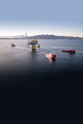
Smart tech to deliver fastest upstream start-up for Aasta Hansteen’s first gas production

Innovative technology is estimated to save 40 days in the commissioning phase by reducing manual interventions by 98%.

ABB is set to deliver what it believes to be the world’s fastest start-up when Equinor’s Aasta Hansteen gas field begins operating and produces its first gas. The firm is in the final phase of providing a suite of ABB Ability digital technologies for Aasta Hansteen, which is located in 1,300m of water in the Vøring area of the Norwegian Sea, 300km from land.

Part of the challenge for ABB was to make the first gas start-up process as quick and efficient as possible. For this, it needed to reduce a sequence of over 1,000 manual interventions to as few as possible. The outcome is a series of buttons that are as simple as starting a car.

“Our teams went through the start-up steps, identified and defined obstacles that needed to be improved, then used our ABB Ability System 800xA simulator to do a virtual start-up of the plant,” explains Per Erik Holsten, MD for ABB Oil, Gas and Chemicals. “At this stage we made a lot of improvements for starting up and operating the plant. Through automating much of the process we managed to reduce a complex set of manual interventions to just 20, which means we are all set to deliver what we believe to be the world’s fastest start-up at first gas.”

The company estimates it saved about 40 days (or nearly 2,700 man-hours) in the commissioning phase of the project by using the simulator to identify and improve 57 areas in the start-up.

The simulator is a solution that minimises risk and reduces the occurrence of unplanned shutdowns, while improving safety, productivity and energy savings. It has a control system that is disconnected from the physical process and is instead simulated by a dynamic process model. By seamlessly extending the distributed control system (DCS), the ABB system provides the same look and feel as the core functional areas. It is a scalable solution in system size, functionality and control system connectivity and is available in three editions: Basic, Premium and Professional.

“In the operation of oil and gas projects there are lots of different automation and instrument competencies and disciplines required for the project to run smoothly,” Holsten says. “In upstream greenfield sites such as Aasta Hansteen, ABB is one of the few companies that is sufficiently skilled and resourced to connect the different parts of the jigsaw together to provide a truly connected plant. Aasta Hansteen is a great example of how it is possible to do just that, while making the start-up and operation of the plant more efficient.”

The solution is part of a much bigger suite of digital technologies being implemented by ABB at Aasta Hansteen. These include a condition monitoring system to monitor more than 100,000 maintenance conditions from more than 4,000 pieces of equipment, tools for alarm management and alarm rationalisation, delivery of several safety critical applications, data storage solution to store all alarms and events easily, and third-party system integration of essential data traffic.

Images: 

Offshore Asset Protection With Anti-Corrosion Coating

$
0
0

An advanced anti-corrosion coating is being used successfully on two North Sea offshore platforms

In a collaborative effort designed to improve vital protection of offshore assets, the Oil & Gas Technology Centre (OGTC) in Aberdeen, UK is successfully conducting trials of an advanced anti-corrosion coating on two North Sea offshore platforms.

The mission of the OGTC, which is jointly funded by the UK, Scottish and Aberdeen governments, is to establish a culture of innovation that will consolidate Aberdeen and North-East Scotland’s position as a global hub for oil and gas technology and innovation.

The challenge, however, is that the UK’s North Sea is one of the most brutal climates in the world. Often ice cold and windswept, the rigs in the North Sea face a constant corrosive onslaught of waves and salt spray.
 
Traditional coatings simply cannot withstand the environment. The cost of maintenance on a rig can be up to 100 times as expensive as land-based maintenance because crews and supplies often have to be helicoptered out to the site, so when coatings fail it costs the asset owner enormous amounts of money.

After extensive research, OGTC identified a spray-applied inorganic coating called EonCoat, from the USA-based company of the same name, as a method of delivering long term protection for the offshore assets. The anti-corrosive coating represents a new category of tough, chemically bonded phosphate ceramics (CBPCs) that can stop corrosion, ease application and reduce offshore platform production downtime even in humid, storm or monsoon-susceptible conditions.

OGTC worked with EonCoat’s UK distributor and applicator, SPi Performance Coatings, to implement two trial programmes. With OGTC’s vision and sponsorship, SPi applied EonCoat to a Total E&P platform and a Nexen platform, each of which is located on the UK continental shelf in the North Sea. Total is a global integrated energy producer and provider, and a leading international oil and gas company, with operations in more than 130 countries. Meanwhile Nexen is an upstream oil and gas company responsibly developing energy resources in the UK North Sea, offshore West Africa, the USA and Western Canada.

Total E&P trial

SPi applicators, along with EonCoat material and equipment, were helicoptered to Total’s Elgin ‘A’ Wellhead platform on December 17, 2017. The coating was applied to areas of the platform’s lower deck that were suffering from severe corrosion, and a topcoat was added for aesthetics.  

Surface preparation for the trial was carried out by Muehlhan, a global provider of surface protection and industrial services with operations in shipping, oil and gas, renewables and industry/infrastructure segments.

In the trial area, the existing coating system was completely removed from structural steel tubulars and flat plate. The structure was power washed and degreased to remove contaminants.  All tubulars were blasted to SA2.5, and flat plate mechanically prepped to ST3.  

Although rust rashing was visible on areas prior to spray application of the anti-corrosion coating, this was deemed acceptable due to the coating’s particular properties. It can be applied to a damp substrate with rust rashing/flash rusting, and high salt levels do not degrade the coating, which reduces surface preparation requirements.  

The coating can cure in a single coat 15 minutes after application, depending on climatic conditions, which expedites completion, compared to traditional coatings, which require extensive drying time between coats.

In contrast to traditional coatings, which only form a physical barrier to corrosion until breached, EonCoat chemically bonds with bare substrate surfaces, providing an iron magnesium phosphate layer that prevents steel corrosion. This process provides a very thin layer (about 2 microns) of permanent protection. A second layer – a tough ceramic outer shell – provides further protection, and also acts as a reservoir to re-phosphate the steel if needed. This ensures the alloy layer remains intact, and allows it to “self heal” if it is ever breached by mechanical damage.

During this ongoing trial, testing has been done via cross cuts of about 6-8in in length down to the substrate to provide evidence of EonCoat’s self-healing properties.

Nexen trial

After the early success of the Total E&P trial, a second offshore trial is now being conducted. SPi applicators, as well as EonCoat material and equipment, were helicoptered to Nexen’s Buzzard platform on June 18, 2018.
 
After Stork, a Fluor company and global provider of integrated operations, maintenance, modification and asset integrity solutions, assisted with fabric maintenance and surface preparation, SPi applied the anti-corrosion coating to platform areas suffering from severe corrosion.  

Although results from this second trial are still under consideration, they look extremely promising.  

“As oil and gas E&P companies look to combat offshore asset corrosion, extend safe production and reduce the need for costly maintenance and downtime, we look forward to working with OGTC, Total, Nexen, Muehlhan, Stork and other platform owner/operators in the North Sea,” concludes Merrick Alpert, president of EonCoat.

Images: 

Benefits of a chemical injection package on vibration emissions

$
0
0

Yves Marinoff describes how a chemical injection package enables MEG injection for extraordinary requirements on vibrations and noise emissions

The thirst for the coveted raw product of natural gas remains unquenched, despite the crisis in oil and gas. Each year, the global quantity of drilling platforms increases – their number has gone up by 25% in just the past seven years alone. In the course of this, locations in coastal regions or in the vicinity of animal nesting areas have also been developed. As a result, the pressure on manufacturers of platform components to adapt their products to environmental demands is on the rise.

These manufacturers must ensure a safe process without disturbances while at the same time providing for the greatest possible protection of people and nature. This requires a departure from standard solutions towards an increasingly flexible product design, one that takes governmental regulations, standards and customer specifications into account - all of which are currently rising greatly in stringency. For this reason, Lewa relies upon intensive project management and excellently trained engineers for its chemical injection packages, to optimise the customised design engineering with regard to factors such as noise emissions and vibrations, as well as the prevention of leaks.

From the date of their discovery in 1811, gas hydrates were overlooked for nearly 100 years after as having been only a “chemical curiosity” – until gaining relevance at the beginning of the 20th century as the result of ice-like entities causing pipelines to break down. In the meantime, this problem was met with the injection of various substances – what are referred to as inhibitors. Monoethylene glycol (MEG) is among them. This organic compound has the benefit that it is not only suitable for the prevention of hydrate formation, but also for gas drying. Furthermore, MEG can for the most part be reclaimed from the process, thus being capable of being reused. Not only does this help to preserve the environment, it also lowers the necessity of transporting the chemical to drilling platforms.

Tried-and-tested system in customised design variations

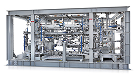
Due to the two MEG application options, it can be used on an oil rig for two components. For one, it is intermittently injected into the borehole top between the upper main valve and the throttle valve to prevent the formation of hydrates. For another, an injection into the cooler of the gas export compressor for the purpose of gas drying is possible. The process is usually carried out at low flow rates by means of diaphragm pumps – at large quantities by means of plunger pumps – that are installed with tanks, piping and instrumentation, all the way to integrated chemical injection packages, exemplified by Lewa. Among other advantages, this has the benefit of being able to take the interactions between individual components into account in the course of an overall optimisation effort.

Whereas the process planning is the responsibility of the specific engineering company, it is the manufacturer who needs to undertake the detailed engineering in accordance with the tenders. The difficulty here is to bring the often highly complex, necessary standards – for example, in relation to environmental protection and operating safety – into accord with the directives and laws that are applicable at the location of use, as well as with customer specifications. In most cases, engineering solutions must be found that diverge from customary solutions. For this purpose, Lewa employs engineers from various disciplines such as hydraulic systems engineering, mechanical engineering and electrical engineering, who contribute to the evolution with their expertise, thus being able to react with flexibility to the most diverse regional conditions.

Keeping negative influence on the environment at a minimum

Most importantly, the harsh sea environment makes special designs necessary. The extremely salty atmosphere makes the use of corrosion-protected materials essential. This is why the company uses materials such as stainless steels for production, in special cases also using duplex or super duplex stainless steels. Owing to the limited space available on an offshore oil rig, it is mandatory that all components such as the pump and fittings are designed to be as compact as possible while simultaneously being conveniently operable.

Furthermore, the system should have as little of a negative influence on life and work quality, as well as on the environment, as possible. This can be achieved by the reduction of noise emissions, which in some circumstances are carried on through structure-borne sound, as well as the reduction of vibrations. One customer desired an especially quiet package. For this purpose, Lewa carried out a corresponding study and searched for possibilities relating to acoustic decoupling. Finally, vibration mats in combination with noise hoods were used. As such, sound emission was lowered from 93dB to 75dB.

In addition, for the minimisation of pressure pulsations, the system was submitted to an evaluation in accordance with API 674 Approach 2.

Prevention of leaks

Since MEG is toxic, the highest requirements are placed on process safety and the absence of faults when handling the substance. For this reason, diaphragm pumps are especially well suited. They are hermetically tight and do not tend toward leakage. Occasionally, however, plunger pumps may be required if, for various reasons, diaphragm pumps cannot be employed or in the event of large flow rates. These are only able to be dynamically sealed by means of packings, which is why special precautions need to be taken in such cases to prevent leaks. For example, in having built a system in accordance with the EU Pressure Equipment Directive (DGRL) for one customer in particular, the company deployed a special leak monitoring system alongside a leakage pan together with outlet drainage in a closed drain system: since commercially available flow meters reach their limits in quantities that are so relatively small, the manufacturer determined it was better to go with measurement using radar.

A reduction in maintenance effort also contributes to an increase in process safety. This is why Lewa skids are fully automatic and mechanically redundant, designed for very long operational durations while featuring a fully monitored leakage system. Moreover, high-quality fittings and instruments provide support. Some of these have self-diagnostic systems available. Thus, work that is necessary is reduced to a minimum.

Due to the wide variety of requirements – both those stipulated by the client and those laid down by law – Lewa relies on detailed planning and administration by its project management department, which, for example, takes over administrative tasks such as the coordination of subcontractors, progress supervision as well as documentation for the oil and gas industry.

Yves Marinoff is with Lewa

Images: 

The ‘what, where and how’ of gas monitoring at refineries

$
0
0

Bengt Löfstedt reviews the ‘what, where and how’ of gas monitoring at refineries

Gas concentration monitoring at refineries can be of importance for safety reasons, but it’s also essential to control production quality, to minimise losses and thereby production costs, and to meet environmental objectives, potentially with reduced pollution and improved health as results.

Which gases to monitor depends on the production processes in play, and where the monitoring is to take place. For process control purposes, a range of hydrocarbons such as methane (CH4) and benzene (C6H6) can be of interest, but also for example carbon monoxide (CO), carbon dioxide (CO2), water (H2O), and hydrogen sulphide (H2S). The concentrations can range between 0 and 100%.

Tail gas monitoring, i.e. the emissions of air pollutants at the end of the production processes, might cover the same gases that are of interest for process control. However, the tail gas often undergoes some combustion process, for example in an afterburner, and other types of gases might also be monitored. This can include for example sulphur dioxide (SO2), nitric oxide (NO) and nitrogen dioxide (NO2). The pollutants at this stage are usually measured in parts-per-million (ppm) ranges. Gas monitoring is sometimes combined with flow monitors to yield the total emissions of pollutants in units of weight-per-time. The driving force behind emissions monitoring is often requirements from legislators and environmental authorities, requiring proofs of emissions limits being observed.

A third application area for gas monitoring is surveillance of the ambient air close to the production facility. When done for personal protection, it is often done with wearable monitors of one or a few hazardous gases, such as CO or H2S. If the concentrations approach dangerous levels, often in the ppm range, the monitor can issue an alarm and the wearer can leave the area before being affected by the gas.

Air quality monitoring (AQM) for the general benefit of the staff at the facility or the inhabitants of the neighbourhood is often based on permanently installed AQM stations. This type of monitoring reveals the long-term exposure to air pollution, often in levels of parts-per-billion (ppb). The types of pollutants to monitor are often the same as those found in the production process, including SO2, NO2 (NOx), benzene, and H2S, but other pollutants of concern such as ozone (O3) and particulate matters can also be monitored, while at it. At best, AQM shows pollution levels well below limits set by the legislators. AQM can be initiated by local authorities wishing to monitor and protect the public health, but it can just as well be on initiative from the facility, to (hopefully) show that the air pollution levels are limited and under control.

An AQM station used for general, long-term monitoring can double as an alarm system for accidental releases of air pollutants from the refinery. This allows countermeasures to be taken, at best long before any staff member or neighbour is affected by the release. Further, an AQM station can also be used to substantiate diffuse emissions occurring from leakages in e.g. pipes and valves. In combination with monitoring of wind speed and wind direction, pollutants can be back-tracked to specific source locations, revealing unknown or excess leakages, and ensuring that proper actions can be taken to stop or reduce the emissions.

So, how are the gas concentrations monitored? It depends on gas type and concentration range. However, in most cases, the measurement devices use the optical properties of the gaseous molecules, looking at absorption light. The more absorption of gas-specific wavelengths, the higher concentration of that gas.

Two types of instruments exist: sampling, which uses pumps, tubing and often pre-treatment of small gas volumes before the absorption is measured in an internal cell, and in-situ (“at place”) where the absorption is measured by sending a light beam through the actual gas monitored (“open-path”).

Open-path monitors have several advantages over sampling instruments, in particular for permanent AQM applications. A sampling instrument captures the gas in a single inlet point. If a plume of an emitted gas does not pass that point, the emission will not show. In contrast, the monitoring results from an open-path instrument are average concentrations along the light beam, often several hundred metres long. A series of light beams can form an optical fence around the facility, capturing the plume no matter of its direction.

A single open-path system can often use several beams of light and monitor multiple pollutants. In contrast, sampling instruments are often designed to measure concentrations of just a single pollutant, resulting in rapidly increasing costs also if just a few types of gases are to be monitored in a few measurement points. In addition, a sampling system often requires more frequent maintenance and more consumables, compared to an open-path system. The latter might come with a somewhat higher initial price tag, but in the long run, the total cost of ownership is more favourable for open-path systems. The low maintenance requirements also make open-path systems less prone to handling errors, giving more uptime and reliable monitoring results.

In the end, the choice of instrument depends on what to monitor, and where to monitor it. A good supplier with good references will provide guidance to the best monitoring solution for the specific application.

Bengt Löfstedt is with Opsis

Images: 

Straight flowmeters in demand for oil and gas applications

$
0
0

Frank Grunert explains why straight tube Coriolis mass flowmeters are increasingly specified in oil & gas applications

Oil & gas is one of the biggest markets for high-capacity Coriolis mass flowmeters. Their unrivalled accuracy of mass flow and density measurement with both liquids and gases, lack of moving parts and low maintenance makes them particularly suited to loading, unloading and other volume transfer applications, including custody transfer.

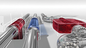
One of the biggest challenges when it comes to installing large line-size Coriolis flowmeters is space. Until recently, the rule was that the bigger the flowmeter, the greater the space required. Traditional bent tube high-capacity meters (shown in red in the image below) often require complex pipe layouts, elevation of the line or groundworks to accommodate them. The latest generation of straight tube meters, shown in blue in the image, provide a solution to this problem. In many projects, the diameter of the meter body is almost identical to that of the pipe, meaning that they can be fitted as part of the pipe run with minimum adaptions, which simplifies installation.

The flexibility offered by the compact envelope of the straight tube design makes these meters ideally suited to applications where space is at a premium. Compact and remote designs are available for ease of operation. Many installations would not have been possible with large line size bent tube flowmeters due to the lack of space.

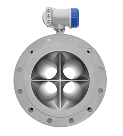
Another benefit of the straight tube design increasingly recognised by design engineers is the role they can play in reducing overall system pressure drop. By definition, bent tube meters have a greater pressure drop than straight tube models and the additional pipework and fittings required to install them can add significantly to the overall total. The novel four straight tube design of the Optimass 2400 S400 with optimised flow splitter not only gives it a low pressure drop but also a high flow rate at up to 4600 t/h.
 
In addition, unlike their bent tube cousins, straight tube meters are not susceptible to the Bourdon effect where the bend has a tendency to “open” under pressure and create stresses in the end loads of the meter. Optimass 2400 also have strain gauges mounted on the measuring tubes to compensate for hoop stress, making the meter less sensitive to process pressure changes.

Flowmeter choice is often a compromise between performance and budget, but the purchase cost of the flowmeter alone can no longer serve as the major focus. Depending on the time required, labour can represent up to 70% of the total cost of installation. By reducing installation complexity and the resulting savings in labour and materials, straight tube Coriolis flowmeters are delivering additional value for the contractor and ultimately the owner. Furthermore, the reduced need for maintenance, cleaning and inspection means that the total cost of ownership of straight tube Coriolis mass flowmeters can be considerably less compared to other technologies.


Frank Grunrt is with Krohne

Images: 

New oil research lab opens in Rio

$
0
0

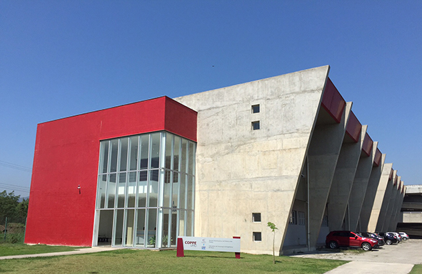
A laboratory hoping to guarantee an increase of 22 billion barrels of oil in Brazil’s reserves has opened at Ilha do Fundão, in Rio’s Northern Zone. The Advanced Petroleum Recovery Laboratory, inaugurated by Coppe, a research unit of the Federal University of Rio de Janeiro (UFRJ), is ready to produce technology that will allow the country to expand its oil production, extracting more resources from the already well exploited reserves.

In the new laboratory, which received investments of R$ 107 million from Shell and R$ 10 million from Petrobras, research will be carried out with the objective of investigating and developing advanced recovery techniques applicable to Brazilian pre-salt carbonate rocks. This is a new area of research, whose results could represent billions of dollars in royalties and new investments in Brazil.

According to data from the National Petroleum Agency (ANP), the oil recovery factor in Brazil is 21%. According to the professor of Coppe’s Civil Engineering Program, Paulo Couto, coordinator of the laboratory, an increase of only 1% in the rate of recovery of Brazilian rocks could represent US$ 11 billion in royalties, generating an increase in reserves and new investments estimated in US$ 16 billion.

According to Couto, the equipment purchased for the laboratory can operate any fluids from reservoirs located at great depths, under 700 times atmospheric pressure and up to 150ºC. “We have unique equipment, a porous media flow greenhouse, equipped with an x-ray scanner, which will allow dynamic images at high pressure and a high temperature of oil flow in carbonate rocks. A unique dataset in the world, that does not exist in the literature, and the UFRJ and the Heriot-Watt University stand out as pioneers in this field”, he said, highlighting the partnership with the Scottish institution.


Images: 

Giant reactor off to Nigerian oil refinery

$
0
0

Godrej Process Equipment has shipped one of the World's tallest Continuous Catalytic Regeneration (CCR) Reactor to Dangote Oil Refinery, Nigeria. At 95 meters high, the CCR Reactor weighs approximately 703 metric tonnes, nine times heavier than a space shuttle.

CCR is the key process in oil refinery converting low value naptha to high valuable products like petrochemicals and gasoline through various reactions such as dehydrogenation, aromatisation, isomerisation, dealkylation, dehydrocyclization. The CCR Reactor is a tall column with a continuous moving catalyst. Very stringent tolerances are required to be maintained for installation of reactor internals. The equipment being in Hydrogen service, calls for a very critical metallurgy (Chromium Molybdenum Steel) leading to a very complex fabrication requirement.


Images: 

New order for reinvigorated steel works

$
0
0

Liberty pipe mills at Hartlepool, England has won a multi-million pound contract to supply steel pipeline for North Sea gas.

The mills, which were acquired and relaunched by Liberty, part of Sanjeev Gupta’s GFG Alliance, in late 2017, have just begun making the first batch of a total order for 12,000 tonnes of 24 inch steel pipe from global engineers Subsea7, that will be used in the Shell Shearwater gas field over 200 miles off the coast of Scotland.

Over the next few months workers at Hartlepool will make around 22 miles of heavy-duty pipe that will lie 90 metres under the sea, helping channel millions of cubic metres of gas each day to the huge St Fergus onshore terminal in Aberdeenshire.

This order, along with the Subsea7 contract to provide large diameter steel pipe for Equinor’s Snorre Expansion Project off the coast of Norway, is among the largest contracts secured by the Hartlepool mill since its acquisition by Liberty. It will ensure that both the 42 inch and 84 inch mills at Hartlepool have full order books as the operation moves into the Spring. 

Order books for both mills were also bolstered in recent months by major contracts totalling over 20,000 tonnes of pipe from the USA, one for the energy sector and another for the construction of chemical giant Lyondell Basell’s new showpiece plant in Texas.  

The comeback of the mills, which suffered badly during the downturn in the steel industry over recent years, has seen job numbers grow from 120 up to 200 over the past few months.


Tags: 
Images: 

Scottish 3D printer opens for business

$
0
0

Angus 3D has produced its first pieces using a Markforged Metal-X metal printer.

 
The Metal-X uses Atomic Diffusion Additive Manufacturing (ADAM) technology – where metal powders are encased in plastic binders and then melted off to create designs previously impossible to manufacture and with unprecedented levels of detail as well as faster and at a fraction of the cost.
 
The Metal-X can also reduce the weight of traditional manufactured parts while maintaining their strength and performance by producing them with unique geometrics, such as closed-cell honeycomb infill. By printing metal powder in a plastic matrix, the it also eliminates the safety and environment risks associated with other 3D-printing methods.
 
Parts printed with the Metal-X are also up to 10 times less expensive than alternative metal-additive technologies and up to 100 times less than traditional fabrication technologies like machining or casting. Materials costs are typically reduced by up to 98%.
 
So far Angus 3D has used the Metal-X to print lightweight custom parts for a bicycle business and components for a new product design for an oil & gas company as well as remanufacture obsolete components for a local textile manufacturer to help maintain production and reduce breakdowns. It’s also producing test pieces for an F1 team looking for help carrying out performance analysis on parts.
  
Angus 3D’s Metal-X will further advance the circular economy by allowing parts which would previously have been scrapped due to obsolescence to be put back in service through reverse-engineering – where their design is replicated using a 3D scanner and then printed using the Metal-X. It also improves the benefit to the circular economy by using less resources in the process.
 
For example, an oil and gas company which had been scrapping electrical connections due to minor parts no longer being available is now having the parts reverse-engineered and remanufactured, allowing the connectors to be put back in service, saving nearly £20,000.


Images: 

Protection system for gas pipelines in the UAE

$
0
0

Presenting a recent case study, Chris Todd explains how three types of protection system for gas pipelines were deployed in the UAE

DUSUP (Dubai Supply Authority) recently specified a particular liquid epoxy coating for a buried gas pipeline project in Dubai, UAE. The project was undertaken by the main contractor Global Technologies Projects and Services (GTECH) with help from subcontractors Al Raha Metal Products Factory,  Al Raha Mechanical Equipment and WLL (Arm group of companies).

DUSUP required three solutions for three different types of infrastructure. Having already specified Denso Protal 7200 for the 24in diameter block valves and straight pipe lengths, it asked Denso to provide additional systems for the 2in diameter connecting valves and pipe tie-ins. Winn & Coales’ (Denso) lengthy experience in corrosion prevention enabled it to provide the following solutions.

System 1 (epoxy), for the 24in diameter block valves plus straight pipe sections.

The surface was abrasive blast cleaned to a clean near-white finish, SSC-SP 10/Nace No 2. An appropriate angular grit was used to achieve an anchor profile (63 to 127 micron). Chlorides were removed to an acceptable level of below 3 micro grams per cm2. A coat of Protal 7200 was then spray-applied over the entire area to a minimum of 508 microns and a maximum of 1,270 microns, in accordance with DUSUP’s specification.

System 2 (petrolatum), for the protection of the 2in diameter valves. After a thorough cleaning of the valve surface removing all dust, dirt and loose matter, a coating of Denso Paste was brush-applied over the entire area. This was followed by an application of Densyl Mastic to fill any voids and irregularities, creating a smooth surface for the following tape wrapping. Next, a spiral wrap of Densyl Petrolatum Tape with a 55% overlap was applied over the valve. A final spiral wrap of Denso PVC Outer Wrap with a 55% overlap completed the protection system.

System 3 (bitumen), for the protection of the pipe tie-ins. After the existing coating was profiled to a 20° angle, all dust and sand contaminates were removed. A brushed coat of Denso Primer D was then applied to the pipe area to be protected at a minimum of 150mm either side of the coating interface and allowed to dry. This was then followed by a spiral wrap by hand or pipe wrapping machine of Densopol 60HT Bitumen Tape with a 55% overlap. A final spiral wrap of the Denso PVC Outer Wrap was applied by hand or machine with a 55% overlap to complete the protective system.

Images: 

New tractor for submerged arc welding

$
0
0

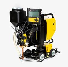
Versotrac’s modularised components can be disassembled into smaller units, hand-carried into confined or remote spaces and then reassembled in minutes. No tools are required.

“This modular tractor system recognises the portability needs of ship, barge, offshore, wind tower and structural steel applications. Versotrac is a truly modular welding tractor, allowing users to take it anywhere without the need for cranes or other lifting devices,” said Magnus Svedlund, Global Product Manager SAW Equipment, ESAB.

The Versotrac can be rebuilt for optimum beam welding positions (including fillet welds in the flat position), comes in four- and three-wheel versions and can be adapted for both inverter-based AC/DC power sources and conventional DC and AC power sources. A new wire spool handling system detaches for easier transportation and more ergonomic loading of wire spools, while steering handles let operators easily change weld point position.

Quick-connect welding head

ESAB further enhanced the modular design of the Versotrac with its EWH 1000 welding head and EAC 10 controller, both of which detach. Their associated quick connectors and automatic detection/setup by the controller let users switch between the SAW, GMAW and Gouging processes in seconds.

The Versoarc EWH 1000 welding head incorporates a wire feed system that can weld with single wires up to 5mm and up to 1000A @ 100% duty cycle. For higher productivity (20+ kg/hr deposition), the Versoarc EWH 1000 can be used with twin wire process. A closed-loop encoder control system ensures precise wire feed speed control.        

It uses the entirely new and intuitive EAC 10 controller. Its simplified interface includes functions users need for tractor-based and other light-automation applications, making more room on the display for important functions like real-time, on-screen heat input to monitor and control weld quality. The EAC 10 pendant detaches from the base control unit so operators can work in a comfortable position and change settings from a distance. The controller works with all current ESAB submerged arc welding power sources, as well as most analog power sources on the market.


Images: 

Flex-Hone plays critical role in oil & gas industry

$
0
0

In the oil & gas industry, failing to perform ongoing maintenance on equipment can have severe consequences including reducing equipment service life, causing unplanned shutdowns and degrading performance, writes Denell Gibson. Ongoing maintenance is required to remove rust, corrosion and other accumulated material from the inside diameter (ID) of valves, pumps, piping, diesel engines, motors, natural gas compressors, flow meters and other large bore equipment. Often, this maintenance work is performed in the field under harsh conditions.  

Large diameter Flex-Hone tools are the ideal solution because they can be run with virtually any rotating spindle, are self-centring, self-aligning to the bore and self-compensating for wear.

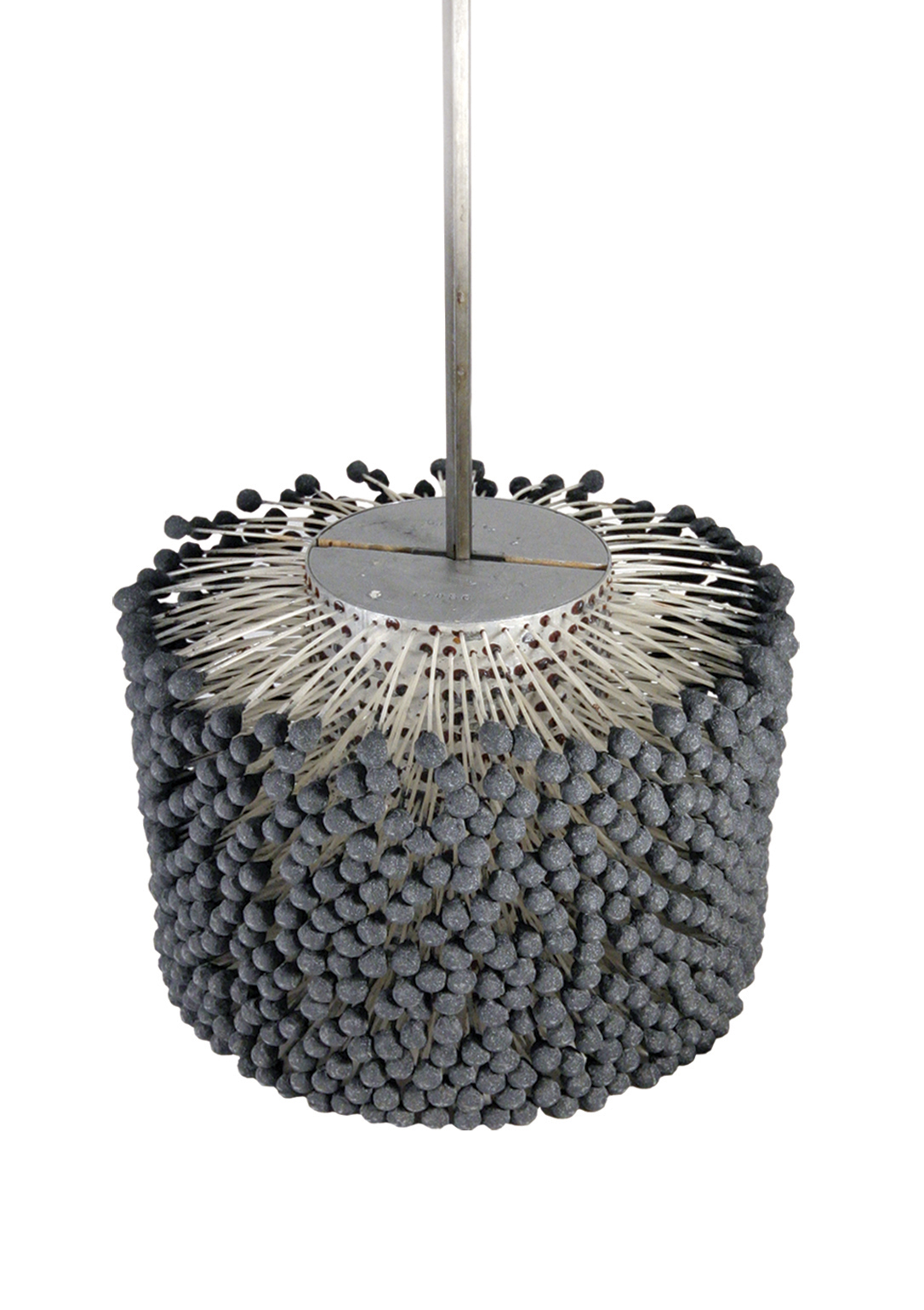
The Flex-Hone tool is a resilient, flexible honing tool with a soft cutting action that provides a superior surface finish with a non-direction or crosshatched pattern. Whether it’s deburring a hole or blending an edge, removing corrosion or machining marks, using the tool results in increased product performance and longer product life. The Flex-Hone is designed for a variety of automotive, hydraulic, pneumatic and industrial applications in standard sizes as large as 36 inches.


Images: 

Huge gas separator moves toward completion

$
0
0

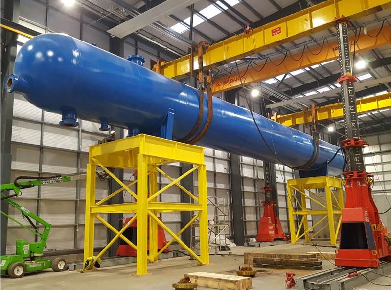
TUV SUD NEL has just invested £1.45million in one of the world’s largest gravity test separators, as part of the build programme for its new Advanced Multiphase Facility (AMF).

 
The new separator will test both multiphase and wet gas flows (oil, water and gas) and will ensure sufficient retention time, even at the largest flow rates. Weighing 270 tonnes and operating at pressures up to 150 bar, it will enable flow rates within the AMF that are 20 times greater than the performance of any other test facility in the world. This will meet the oil & gas industry’s growing demand for flow meter testing that more accurately reflects real-field conditions, to reduce measurement uncertainty and minimise fiscal inaccuracy.
 
Infrastructure Manager, Muir Porter, is leading the installation project and said: “This is a major milestone for us as the test separator is at the heart of the AMF construction project. The next major phase will be to build the complex steel pipework which forms the test loop and feeds into the test separator, and which will deliver a multiphase flow test facility with a range beyond anything currently available on the market.”
 
The £16million AMF will focus predominantly on the £50-billion-per-annum global subsea sector and wet gas business. It will facilitate company-led industrial projects and product development, hands-on industry training and academic research. Creating at least 17 new jobs, the centre will futureproof the delivery of innovative technical services to the oil and gas production market for the next 25 years.
 
Scottish Enterprise has supported the development of the AMF with £4.9 million of research and development funding. Alongside the grant from Scottish Enterprise, TUV SUD NEL’s parent company, TÜV SÜD AG, is investing £11.1 million, which makes the project the largest capital investment to date in the company’s UK business.
 

Tags: 
Images: 

New partnership aims to deliver TCP risers

$
0
0

Oilfield technology firm Airborne Oil & Gas and engineering company Símeros Technologies have signed an agreement which aims to deliver the first qualified Thermoplastic Composite Pipe (TCP) risers in the deepwater region Brazil.

 
Last year, Airborne Oil & Gas commenced its TCP riser qualification program. The technology is believed to be a world first for fully bonded, free hanging composite risers with the aim of providing a disruptive new riser pipe technology for operators with international deepwater applications.
 
The program is receiving funding from a major operator in the region and is aimed at qualifying the TCP riser for dynamic deepwater applications, including for pre-salt and highly corrosive conditions, against an ambitious timescale.
 
The TCP flowlines and risers developed by Airborne Oil & Gas can be installed by existing flex-lay and reel-lay vessels and be installed in the flexible and cost effective free hanging catenary mode. “Installed in free hanging catenary configuration, our TCP Riser provides the opportunity for significant savings on typical FPSO development, through faster installation and avoiding the need to use buoyancy modules”, said Oliver Kassam, Airborne Oil & Gas CEO.

Read about bearing requirements for risers here.


Tags: 
Images: 

Heavylift crane shaves a month off Iraqi refinery project

$
0
0

ALE mobilised a heavylift crane to install three tank roofs, saving over a month from the schedule of a section of the Karbala Refinery Project in Iraq. The new facility is expected to have a refinery capacity of 140,000 barrels of crude oil per day and this operation had a tight deadline to keep the $6.04bn project on track.

The tank roofs had been built inside the tanks and the client initially planned to raise them by air. ALE had previously completed a large scope of work on the project of more than 350 lifts of refinery components, so the client had faith in its expertise. ALE’s ability to quickly reconfigure one of the largest-ever capacity cranes in Iraq presented an alternative option that would save time and enable the client to proceed to its next phase ahead of schedule.

The early involvement of ALE saved costs on the operation as the client didn’t have to purchase heavy duty turnbuckles or additional lifting tackle. ALE worked closely with the client during the design of the lifting tackle arrangement for each roofs’ 20 lifting points. ALE provided recommendations for the client’s design and fabrication of the specialist lifting device that would ensure equal loading of all slings.

Additional time was saved on the operation as, following a lifting study, ALE was able to perform the lifts from only two crane positions instead of three. Due to the high temperatures on site, movement times were limited, but the team’s experience enabled them to reduce the operation from 21 to 15 days.

ALE used a 1,600t capacity crawler crane to hoist each roof, weighing 209t and measuring 53m in diameter. Once at the required height, they were welded in place.

The Karbala facility was commissioned to help fulfil Iraq’s growing domestic demand, as well as assisting in the country’s transition to become a net exporter of oil products. Production at the refinery is expected to begin in 2022.

Read about ALE’s recent Russian success here.


Images: 

How To Reduce Motor Downtime On Offshore Oil Platforms

$
0
0

Constant monitoring of critical motors and generators on offshore oil platforms while offline prevents failures on start-up, reduces production interruptions, saves on rewinding repairs and increases personnel safety

For decades, offshore oil and gas personnel have performed insulation resistance tests with handheld megohmmeters to prevent motor and generator failures that lead to costly unplanned shutdowns, production interruptions and rewinding repairs. However, these tests only provide a snapshot of motor or generator health. In a matter of only a few days, windings and cables that are exposed to salt air, moisture, chemicals, contaminants or vibration can become compromised and fail at start-up.

The Challenges Of Megohmmeters

Portable megohmmeters also require electrical technicians to manually disconnect the equipment cables and connect the test leads on potentially energised or damaged equipment to perform the manual testing. These tests expose technicians to potential arc flashes when they access the cabinet. In the USA, non-fatal arc flash incidents occur approximately five to 10 times per day, with fatalities at the rate of approximately one per day.

With so much at risk, offshore platform operators are recognising the value of continuous megohm testing and monitoring of insulation resistance that initiates the moment the motor or generator is off and continues until it is re-started again.
 
Armed with this information, maintenance personnel can take corrective actions ahead of time to avoid a failure that would interrupt production. By doing so, they can save oil and gas producers hundreds of thousands of dollars in lost production and repair fees for expensive rewinding as well. Furthermore, permanently installed automatic testing devices allow for ‘hands-off’ monitoring without having to access cabinets – keeping technicians out of harm’s way.

How To Protect Motors On Offshore Platforms

Offshore platforms rely heavily on their main generators and a variety of motors, though the number and type vary depending on the size of the platform and rate of production. On a deepwater or ultra-deepwater platform, several hundred motors may be installed, with five-10 categorised as critical or significant (high-cost motors that are not easily replaced). On exceptionally large platforms, up to 30 critical motors might be involved.
 
These motors, which can range from 460V up to 13,200V, are found in crude oil export pumps, circulating water (saltwater, utility, fresh) pumps, fire pumps, cement pumps, gas compressors and fans. Medium-voltage generators in the main power plant, as well as low-voltage standby generators that back up the main generators and power lifesaving equipment are also critical to the operation of the platforms.

Unfortunately, this equipment is subjected to ice, moisture, changing temperatures and dense salt-fog. The salt-fog is one of the worst problems because the salt, combined with the moisture, can cause severe damage to the electrical insulation inside the critical motors and generators.

“The offshore environment is probably one of the harshest environments for electric motors and generators,” says Donna Lee Hodgson, senior electrical engineer for Shell International Exploration and Production. Hodgson currently designs deepwater facilities for projects in the Gulf of Mexico. “I have seen motors come into the shop that have salt encrusted on the interior of the stator windings,” says Hodgson.

Sand is also prevalent on deepwater platforms given the constant sandblasting and re-coating of carbon steel structures. “Basically, the sand that you are blasting at the carbon steel structures around the equipment tends to get into the motors and generators too,” explains Hodgson. The sand breaks down the insulation coatings on the windings, which leads to premature failures. The environment is so corrosive that Hodgson typically specifies enclosed or weather-protected motors.

Preventative Maintenance Programmes

In addition, most offshore oil operations engage in a time-based preventative maintenance (PM) programmes. As part of the programme, insulation resistance tests are typically scheduled on a semi-annual or annual basis. Typically, insulation resistance tests are also conducted at the start of annual overhauls or planned outages, to identify any motors that need repairs.  

According to Hodgson, critical motors on the deepwater platforms are tested to determine the equipment’s Polarisation Index (PI). The PI is used to determine the fitness of a motor or generator and is derived by calculating the insulation resistance of the windings using a portable megohmmeter.

The test begins with a reading of insulation resistance recorded at one minute, then a second test reading is taken for 10 minutes. The ratio of the two measurements provides the PI, which should be above 2.0.

Still, despite these types of tests, motors and generators can become compromised within only a few days in the corrosive, dirty environment and fail at start-up. When this occurs, costs quickly mount for “rewind” repairs or replacing the motor or generator while production comes to a halt. “Failures can be really expensive. Rewinds can cost tens of thousands of dollars, up to a couple hundred thousand depending on the type of motor or generator,” says Hodgson.
 
“And it is not just the cost of the repair,” she adds. “It is also the cost of the labour to get the motor or generator prepped and ready for shipment, the cost for the boat to bring it to and from the platform, and road transport. Those costs can also run in the tens of thousands of dollars.”

To avoid these costs, electrical engineers are turning to a continuous monitoring device, the Meg-Alert. Hodgson says she first heard about the automatic insulation resistance testing device through some of her colleagues.

What Is A Meg-Alert?

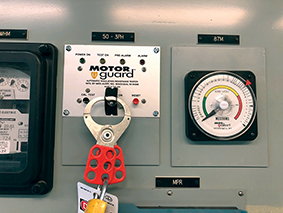
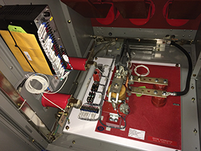
The Meg-Alert unit is permanently installed inside the high-voltage compartment of the MCC or switchgear and directly connects to the motor or generator windings. The unit senses when the motor or generator is offline and then performs a continuous dielectric test on the winding insulation until the equipment is re-started. By testing continuously, it reduces the need for manual PI testing since the insulation resistance readings are averaged over a longer period of time to determine the true ‘leakage current’ level of the insulation.

The unit functions by applying a non-destructive, current limited, DC test voltage to the phase windings and then safely measures any leakage current through the insulation back to ground.  The system uses DC voltage levels of 500, 1,000, 2,500 or 5,000V that meet the IEEE, ABS, ANSI/NETA and ASTM International standards for proper insulation resistance testing voltage based on the operating voltage of the equipment. The test does not cause any deterioration of the insulation and includes current limiting technology that protects personnel.

The Meg-Alert device can also be installed to disable the start circuit to prevent the motor or generator from being operated if the insulation resistance level is unsafe for operation. It is for this purpose that Hodgson installs the device on the generators on the deepwater platforms. “The Meg-Alert is wired to the start circuit so when you hit the ‘start button’ you get an automatic insulation resistance test and if it doesn’t stay above a certain setpoint, it will not start the generator,” explains Hodgson. “What that does is take human error out of the equation.  No one has to remember to use a megohmmeter before starting up the generator – the test is automatic and the equipment will not start if it’s not safe to use,” says Hodgson.

The Benefits Of Hands-Off Monitoring

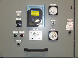
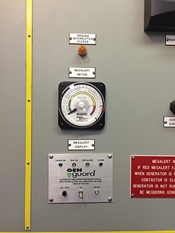
The continuous monitoring system also allows for a hands-off approach that does not require service technicians to access control cabinets to perform a manual insulation resistance test. Instead, an analogue meter outside on the control cabinet door shows the insulation resistance megohm readings in real time. The meter also indicates good, fair and poor insulation levels through a simple “green, yellow, red” colour scheme. When predetermined insulation resistance set point levels are reached, indicator lights will turn on to signal an alarm condition and automatic notifications can be sent out to the monitoring network.

“With the Meg-Alert, personnel do not have to open junction boxes and connect a megohmmeter to the motor or generator. They can just look at the meter and alarm lights on the panel,” says Hodgson.

Continuous monitoring also indicates if the heaters used to maintain thermal temperatures and prevent condensation from forming on the stator coils and cables are working properly. If these heaters fail to operate properly or the circuit breaker is tripped, maintenance personnel may not be aware of it until the motor or generator fails on start-up. Although these heaters are checked regularly, this can leave critical motors and generators unprotected for weeks or even months.

How To Prevent Arc Flashes

According to Hodgson, safety is another major driver behind the decision to install the Meg-Alert devices. Arc flashes are an undesired electric discharge that travels through the air between conductors or from a conductor to a ground. The flash is immediate and can product temperatures four times that of the surface of the sun. The intense heat also causes a sudden expansion of air, which results in a blast wave that can throw workers across rooms and knock them off ladders. Arc flash injuries include third degree burns, blindness, hearing loss, nerve damage, and cardiac arrest and even death. Among the potential causes of an arc flash listed by NFPA 70E includes “improper use of test equipment.”

Although de-energising equipment before testing and wearing appropriate personal protective equipment (PPE) is recommended, the best solution is to eliminate the need to access the control cabinets at all to perform insulation resistance tests. “Two hazards we would be concerned about on a platform are electrocution and arc flash,” says Hodgson. “Given that generators on platforms are located within feet of the load, this is even more of a concern because of the high short circuit currents.”  
 

Images: 

How Safe Are Flanges?

$
0
0

Welding is still the most widely recognised method for joining pipe systems together. However, there’s an additional connection technology that is worth considering: the High Performance Flange (HPF) system.  Ramiz Selimbasic details this time-saving and cost saving alternative to welding.

What Is The High Performance Flange (HPF) System?

The High Performance Flange (HPF) system is coordinated to common pipe sizes from 25 to 150mm diameter and wall thicknesses up to 20mm. It is designed for flange sizes ¾ to 5in hole patterns according to ISO 6162-1/2 (Code 61/62), ISO 6164. High-performance flanges are manufactured as finished machined and type approved according to International Association of Classification Societies (IACS). This therefore results in consistently high precision and quality during processing, so that these components no longer have to be reworked at the installation site.

The best solutions for complex design problems can often be found in nature. The flaring of a tube is similar to the shape of a branch where it joins the trunk of a tree. The tube is flared by hydraulic axial pressure giving it a parabolic shaping, increasing from 10° up to 37°. The initial gentle incline of the shaping guarantees additional safety against strong system vibrations.

The most essential part of the HPF connection is the locking flange design, which supports the pipe from the outside and provides additional protection against it tearing out of the connection. An insert is placed into this specially formed pipe. This insert seals on the connection side either via a special profile seal or an O-ring and on the pipe side via an O-ring. The insert has no toothed contour, which thereby makes repeated assembly work possible without any problems.

The Benefits Of The High Performance Flange (HPF) System?

This HPF principle results in a series of practical advantages as Hans de Lang, production manager at Royal IHC, confirms. In addition to ship construction, the company, which has been in existence since the 17th century, also manufactures pipe systems and accessories for the offshore market and has been using the HPF system.

“The system is universal for working pressures up to 420 bar and is therefore a versatile application method. As we provide solutions for the offshore and underwater markets, this aspect is very important for us. In contrast to conventional O-rings, the special profile seal is particularly resistant to gap extrusion,” says de Lang, thereby highlighting an aspect that is important for his area of responsibility.

“The HPF system is comparatively compact. This refers to the minimum length from the connection to the starting point of the pipe bend. Since we always implement designs that only permit little space and play, the HPF system is a very helpful product for us. Our fitters and assembly workers appreciate the fact that, unlike other mechanical flange systems, HPF inserts can be easily replaced if damaged during installation and pipe forming can be done on site. Also, bolts and screws can be easily tightened even under difficult conditions. All in all, high performance flanges have proved themselves to be tear-proof and vibration resistant. Safety plays a very important role for us,” says de Lang.

Returning to the welding technology mentioned earlier, this traditional technology is comparatively time-consuming, because heavy wall pipes connectors require several layers of welding and must be made by qualified welders. All welds have to have an X-ray inspection and the pipe systems must be flushed through. These intermediate steps can be omitted when using the HPF system, which is also more environmentally friendly. The flanging process does not cause noxious gases, thus eliminating explosion and fire hazards.

How Safe Is The High Performance Flange (HPF) System?

Parker’s HPF components are supplied as standard with a highly corrosion-resistant surface – an aspect that plays an important role across all industries. This surface finish is also free of CrVI, which is suspected of causing cancer.

“Parker always provides a comprehensive service package from design, production and on-site installation that the end customer can take advantage of. But this is not binding on what we can provide. For example, we can also execute pipe end forming ourselves on site with an assembly machine, which makes us even more flexible”, says de Lang. Explaining how the Parker Parflare HPF 120/170 functions, he says: “The machine is used for pipe end forming in the axial pressing process for the HPF flange system. It is a workshop device for single piece production. The flanging contour is achieved by axial pressing of the tool into the pipe end. The contour of the flange is designed for use with HPF inserts.”

The tool’s feed-in movement is generated by a hydraulic cylinder driven by a unit in the machine housing. The return stroke is also executed as electro-hydraulic. The pipes are clamped in clamping jaw sets that are clamped over a cone. The machine is equipped with an adjustable stop end for the pipe end. This therefore produces flange contours of uniform quality. The separated clamping jaws and the pipe stop end enable easy handling and uniform results. The separation of the clamping jaws and the removal of the pipes is facilitated by a bracket. Another practical feature of the Parflare HPF 120/170 is that it can be moved quickly to any location on rollers or by fork-lift truck or crane. In summary, the high-performance flanges can be assembled easily, quickly and, above all, safely.

Ramiz Selimbasic is with Parker


Images: 

How To Fix Bearing Vibration In Offshore Motors

$
0
0

Learn how bearing vibration in an offshore 4MW thruster motor has been fixed through an  innovative joint effort.

Large marine thrusters are vital for the safe manoeuvring of vessels, but their location on board can make maintenance a considerable challenge. So, repairing a failed bearing and housing on an offshore accommodation vessel – as found in a recent case study –would require technical expertise as well as innovative and flexible repair procedures.

Working in the North Sea oil fields, the conditions can be far from favourable, so a safe and pleasant living environment is essential to all offshore workers. Accommodation vessels are co-located with drilling rigs to provide living and recreation facilities for the crew.

The semi-submersible accommodation vessel is designed to house up to 450 personnel. It uses a dynamic positioning system, DP3 in this case, as well as a 12-point mooring arrangement to hold position at sea. The thrusters are a vital part of the system and need to be maintained in perfect operational condition.

Replacing The Bearings

The primary maintenance contractor contacted Sulzer reporting high vibrations in one of the main thruster motors, which are located in the pontoons, after the OEM was unable to support the maintenance request at short notice. The project required the bearings to be inspected and replaced as necessary before recommissioning the thruster motor.

Since this type of repair had never been carried out on this vessel, it was essential that Sulzer carefully surveyed the motor and its location before creating a risk assessment and method statement in line with the vessel’s operational guidelines. The site survey also identified all the tooling and access equipment that would be required to complete the repairs.

The highly skilled site engineering team, based at Sulzer’s Aberdeen (Dyce) Service Centre, put together a detailed plan for completing the project, before flying to Kirkwall in Orkney. From here, the engineers travelled by boat to the vessel and boarded by boat-to-boat transfer.

Accessing The Motor

Once on board, it was apparent that access to the motor would be quite a challenge, with its location in a confined space and the close proximity of bulkheads. The project would require a well-planned procedure to achieve the bearing replacement.

The first task was to disconnect and remove the drive coupling, which was accomplished using the latest technology in induction heating. Jim McClean, Site Services Divisional Manager in Aberdeen, explains: “Heat is required to relieve the interference fit between the coupling and the motor driveshaft. In a workshop environment this would be achieved using gas torches, but due to safety concerns this equipment was prohibited.

“With so much of our work being offshore, we needed a quick and safe method of heating components, and this led us to use specialist induction heating equipment. The system we use has been developed specifically for use in offshore applications and it saves a significant amount of time during repairs such as this one.”

Due to the vertical orientation of the motor, the Sulzer engineers could only repair one end at a time to ensure the rotor was supported during the work. The non-drive end (NDE) bearing was replaced and all the surfaces were inspected and found to be in good condition.

The drive end (DE) bearing was inspected and found to be pitted, and the outer race had been rotating in the housing causing it to also be damaged. As a result, the affected parts were removed for repair.

The damaged housing was immediately shipped to Sulzer’s Falkirk Service Centre, where the machine shop applied metal spray to build up the damaged areas before machining it to the original OEM specifications – all within 24 hours. While the mechanical repairs were being completed, the site engineers on the vessel carried out the electrical tests that had been agreed with the vessel’s owners.

Once the repaired housing was back on board, the engineers rebuilt the motor and reconnected the driveshaft before recommissioning the thruster and taking vibration measurements to confirm the effectiveness of the repair.

McClean concludes: “Working in the offshore environment requires considerable expertise and qualifications as well as a liking of less conventional forms of transport. The customer was keen to repair the thruster motor as quickly as possible and that led to the conversation with Sulzer. With well-equipped facilities and the capacity to work around the clock, we have minimised any downtime and delivered a challenging project on time.”


Images: 
Viewing all 299 articles
Browse latest View live