Quantcast
Channel: Engineer Live - Production/Processing
Viewing all 299 articles
Browse latest View live

How To Improve Shale Gas Well Pressure Stability

$
0
0

Liam Jones details how electric actuators powered by solar panels improve shale gas well pressure stability in USA

The Haynesville/Bossier rock formation dates back to the Jurassic Period and covers large parts of South West Arkansas, North West Louisiana and East Texas in the USA. The formation contains large quantities of natural shale gas sourced from low permeability mudstones.

Why Does The Pressure Stability Need Improving?

Rotork’s customer required an actuation solution to carry out modulating duties on wellhead rotary non-rising choke valves in the East Texas section of the formation. The remote location of the wells meant a system that could operate effectively without a mains electricity supply was specified.

How Was The Pressure Stabilised?

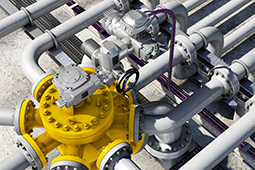
Rotork IQTF electric actuators were installed and powered by a DC supply using a solar system and battery pack. This was considered a more reliable option than hydraulic or pneumatic actuation as it avoids potential leakage common in hydraulic actuators. Electric actuators also use less power than hydraulic alternatives while the long hours of sunlight can be used as a reliable solar power source.

The lightweight, compact IQTF actuator offers fast and accurate valve control and can perform up to 1,800 starts per hour. This was an important factor as a tight well threshold was needed to avoid over pressure in the main trunkline. If too much gas is extracted in a short period of time the reservoir can implode or cause ground fractures which water or gas can infiltrate and cause a loss in production.

Rotork Site Services carried out final commissioning while support was also provided during initial testing and calibration.

The Results

The actuators are controlling the flow and pressure of gas and condensate, a mixture of liquid hydrocarbons formed when pressure and temperature decrease as a result of well drilling, at the site near the city of Lufkin. Two IQTF actuators have been installed on each well to operate choke valves to step pressure down from 10,000 psi to 1,200 psi. The shale gas is metered between the wellhead and midstream trunkline where it is transported to domestic supply customers and industries including LNG plants and power stations. More than 30 are also being held in the customer’s inventory.

Since installation the flow rate at the wellheads has been within a tighter tolerance. This is important to maintain the stability of the well and flow as well as the pressure into the main trunklines.

The IQTF actuators combined with solar systems have proven so reliable that the customer is now using the solution at two of its other production sites, Shreveport in Louisiana and Eagle Ford in Texas.

The actuators are helping the customer produce 190,000 barrels of oil equivalent per day in Texas and Louisiana through activities at both the Haynesville and Eagle Ford basins, as well as the Permian-Delaware basin.

Liam Jones is with Rotork


Images: 

Tackling The Issues Of Entrained Gas

$
0
0

Coriolis mass flowmeters are increasingly specified for entrained gas applications and although they have challenges, leading Coriolis manufacturers have developed technologies that enable their meters to work with two-phase flow. Frank Grunert explains more.

The oil and gas sector continues to face considerable challenges due to the falling and consistently low price of energy. Despite this, companies are expected to maintain high standards of quality and performance while improving efficiency. To meet these challenges, forward-looking firms are turning to cutting-edge technologies to stay competitive.

One proven way to improve efficiency is through accurate flow measurement – which is critical in upstream, midstream and downstream O&G processes. However, entrained gas in liquid (two-phase flow) has traditionally had a significant effect on measurement and performance in O&G applications and although systems are designed to prevent or remove entrained gas, this is not always successful or even practical.

What Are The Problems Of Two-Phase Flow?

Two-phase flow causes problems for most flow measurement technologies. Some are unable to measure at all when entrained gas is present, others will measure the gas as liquid – giving a measurement error proportional to the gas volume fraction (GVF), and others will stop measuring when the GVF reaches a certain level. Adding a further complication, changes in process conditions can cause the flow regime and GVF to shift, making it difficult to predict and manage.

The Challenges of Entrained Gas

Entrained gas presents a particular challenge for Coriolis flowmeters that calculate fluid density from the frequency of the measuring tube as the fluid passes through it. The lower the frequency of the tubes, the greater the density – and vice versa. During two-phase flow the gas and liquid ‘decouple’ and move at different speeds through the flow tubes, which dampens the tube vibration. Varying process conditions also cause the flow regime, GVF and tube frequency to change rapidly.

In the past, this rapid change in frequency caused Coriolis flowmeters to ‘lose’ the signal from the sensors mounted on the measuring tubes. As well as giving wildly erratic and non-repeatable measurement, the meters would often freeze at the last confirmed reading or go into reset mode having assumed that an internal error had occurred, resulting in no measurement of the process.

What Are The Solutions?

The leading Coriolis manufacturers have developed technologies that enable their meters to work with two-phase flow (albeit sometimes with limitations) but have come at the problem from very different angles.

Krohne first provided a two-phase flow solution in 2012, with the inclusion of Entrained Gas Management (EGM) as a standard feature on the MFC 400 transmitter that is fitted to all Optimass flowmeters.

Using high-speed digital signal processing and software-based algorithms, EGM makes constant and precise corrections to the tube driver level based on real-time frequency information received from the sensors and driver feedback. This allows the flowmeter to provide continuous and repeatable mass flow and density measurement across a wide range of gas volume fractions and complex flow conditions. Although Krohne does not specify an accuracy (in the company’s experience, the shifting nature of the flow regime and GVF make each application unique), it does point to the fact that EGM has been successfully proven in use for many years.

Frank Grunnert is with Krohne


Images: 

How To Prevent Pipeline Theft

$
0
0

Pipeline theft is a serious global problem and one that has been on the rise for the past few years. In terms of pipeline integrity, thefts are one of the largest risks that can be hard to prevent without strategic focus. The events in Mexico earlier this year demonstrated the risks thieves will take and the ultimate price some people will suffer as a result. Harry Smith explains how smart technology can help to prevent future thefts.

However, pipeline theft is not restricted to Central and Latin America but extends worldwide, with occurrences in Nigeria, Indonesia and China. In Europe, pipeline thefts have also risen, with incidences found in Eastern and Southern Europe and in the UK. Theft was designated so serious in the UK that the National Crime Agency became involved. The challenge to operators and law enforcement is that there is no single cause of thefts – a wide range of factors including social, economic, political and legal apply. Although some thefts are clearly organised for criminal gain, many are driven by often the most basic of needs, such as obtaining fuel for heating and cooking. It can be these small, ad hoc thefts that can have the worst consequences.

How Do Pipeline Thieves Operate?

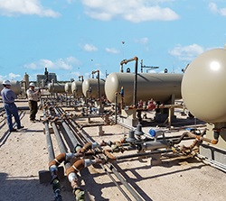
Thieves are becoming more sophisticated and organised, using specialist equipment such as commercial-grade welding machines, calibrated measuring instruments, night vision goggles and vans with modified suspension or exit holes built into the floor of the vehicles. Thieves will also sample product to decide if it is the right product to steal.

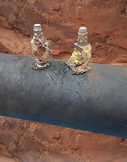
From a technical perspective thieves will deploy several tactics, including: pre-install the tapping point, hose, associated valves and equipment before a pipeline is commissioned; select remote and well-hidden sites such as abandoned buildings such as farms and old factories; bury and cover the hosepipe and all other devices underground. Other tactics include opening the tapping point valves very slowly to generate small pressure change over a long time (known as the patient thieves), and maintaining the theft rate below flow meter repeatability level, e.g. 0.1% of pipeline throughput.

Adding to the challenging in detecting thieves is that they often carry out the activities at night. They frequently steal small volumes each time or inject water into the pipeline while taking oil out. It’s not uncommon for thieves to conduct thefts at multiple locations along the same pipeline.

Thieves increasingly use dangerous techniques, including angle grinding and plastic equipment. At worst, thieves have driven stakes into pipelines and used rags to reduce the flow out of the pipeline.

All of these different tactics make it difficult for pipeline companies to detect and locate thefts quickly and accurately. Although leak detection methods have previously been used for theft detection, a more focused approach is required.

The application of the negative pressure wave, statistical volume balance methods is extremely beneficial for theft detection, with the use of offline analysis and further instrumentation. As every pipeline is different, a ‘one size fits all’ approach is not suitable, however: each technology has its advantages and can often be combined to provide an integrated approach. Furthermore, non-intrusive pressure sensors with remote radio and cellular communications and battery-powered data logging can provide additional accuracy to support GPS location and offline analysis.

Pipeline Theft Detection Solutions 

Avoiding detection is a key target when thieves are going to commence an operation to extract the product from a pipeline. This approach differs from pipeline leaks in several ways: a small amount of product is stolen (ranging from 10 to 3,000 litres); theft flow rate can be less than 0.1%; theft events last for less than one hour usually although occasionally a theft continues unchecked; and the changes in pressure are very small when the tapping point is opened/closed at the end of a long hosepipe.

With these unique characteristics the main requirements of theft detection are: sensitivity (detecting the small product withdrawal); accuracy (locating the tapping point as accurately as possible); and response time (detecting the product withdrawals as quickly as possible). 

Different leak detection technologies can be adapted to meet the above requirements. The main theft detection options are negative pressure wave, statistical volume balance and theft service approach.

Negative Pressure Wave

This technology relies on high-speed analogue pressure sensor readings to identify whether a leak/theft has occurred on the pipeline. The system acquires and analyses the pressure data at a frequency much higher than the typical five-second SCADA rate, capturing data at 60 samples a second. Specialised equipment is thus needed to acquire data at such high frequency.

The main advantages of this system are: accurate leak location within metres of the actual location; short detection time for all leak sizes; and high sensitivity provided through the 60hz sample rate. These are the key features in effectively detecting theft events in all operational conditions.

Statistical Volume Balance

This type of leak detection technology relies on the pressure and flow measurements taken from a pipeline. It uses the existing instrumentation and connects via existing SCADA, PLC or remote terminal unit (RTU) systems. This system monitors the difference between the inlet and outlet flow corrected by the inventory change. This is also referred to as the “corrected flow difference” to determine whether the pipeline is in a leak condition.

The statistical hypothesis testing method is known as the sequential probability ratio test (SPRT). It is applied to the corrected flow difference to decide if the probability of a leak has increased.

The main advantages of this system are a low false alarm rate, the ability to detect leaks under steady-state, transient and shut-in conditions, and accurate leak size estimate. Leak location accuracy is improved through higher data sample rates.

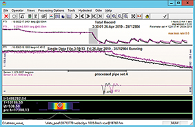
Since the theft rate is usually below the flow meter accuracy and repeatability level, it is difficult for this technology to detect small thefts under running conditions unless false alarms are accepted. The system includes an additional theft module for detecting thefts during shut-in conditions to maintain reliability for both leak and theft detection. The figure on the following page shows an example of it working.

Protecting The Future Of Pipelines

Thefts are not a constant and can fluctuate. Tapping points are often left for years. In the UK a recent tapping point was located that was likely installed as far back as 2015 and left dormant until earlier this year.

When the volume of thefts along a pipeline reduce, it becomes necessary to lower the minimum leak size to be detected. However, in doing this, it can result in increased false alarms as the identified flow and pressure are mostly below the instrument repeatability and process noise level.

An offline service can be offered to pipeline firms. Combining technology with an offline service can provide improved leak location accuracy and sensitivity without unnecessary false alarms.

Deployment of portable and fixed hardware with software solutions allows offline data analysis by an experienced engineer. Through this service, an engineer’s ability to interpret data helps theft to be located down to a few metres, using pressure data collected at 60Hz sample rate and sent to a central location via a cloud-based service.

The data is then filtered to present only the relevant information required and the locations of the illicit tapping points are reported to the pipeline operators.

It is well documented that online leak and theft detection systems must find a balance between sensitivity and false alarms. Some leak detection systems can detect leaks as small as 0.5% of nominal flow-rate without the issue of false alarms. However, this becomes an issue as most theft events are less than 0.3% of the nominal flow-rate. The capability to analyse the data offline has allowed the location and detection of theft to within 5m for thefts as small as 0.1% of the nominal flow-rate in static and running conditions.

Combining a detected theft service with a single or multiple online leak detection system allows for a more reliable leak detection system with the ability to effectively deal with all types of theft events. In the past two years, this combination of negative pressure wave, statistical volume balance and offline analysis has enabled one supplier to successfully detect and locate over 300 tapping points for its clients.
 

Images: 

How To Recover Energy In Crude Oil Pipelines

$
0
0

In some oil pipelines, pressure reduction systems are installed to guarantee a smooth and safe operation (mainly in pipelines with high elevation differences). Such systems convert pressure or kinetic energy into heat. The question is whether it is also possible to transform the kinetic energy into electricity? The answer is yes, as Thomas Rother explains.

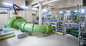
ILF recently had the chance to investigate a potential pipeline system for the installation of a turbine for energy recovery in a crude oil pipeline. The system needed to overcome a hill. To avoid slackline regions, which makes it easier for leak detection and pigging, a back pressure control valve (PCV) was installed. Depending on the pipeline system flow rates the PCV converted energy in the range of 1.5MW to 8MW.


Energy Recovery Configurations In Pipelines

Starting with two pipeline sections, the potential energy that could be recovered was discussed. One main aspect was that the energy recovery system must not influence the goal of the pipeline system: oil transport. Another aspect was that pipelines are normally operated at different throughputs with changing pressure conditions. The resulting system curves needed to be considered when selecting the recovery system, which could be a reverse-operating pump or turbine. In addition, the task of the recovery system influenced the sizing of the energy recovery system. Energy can be produced either for consumers in a demand-driven island-mode or for a grid with a maximum possible energy recovery mode.

In general, systems can be used where pressure reduction or back PCVs are installed. At each pressure reduction valve pressure will be converted into heat, vibration and noise. In the above example a 48in pipeline is considered. A hill (with about 700m height) is located 30km upstream of the storage tank terminal.

Within the project it was decided that only one unit, either one pump as turbine (PaT) or one turbine, should be used. Together with the required power recovery range of between

1.5 and 3.5MW, at all given process conditions (flow/pressure) the task was to find proper solutions for both systems. For a pump there is one characteristic curve. To recover a specific amount of energy the pump must be operated at the corresponding intersection point between the system curve and pump characteristic.

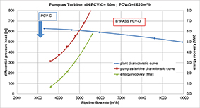
Fig. 1 shows the system curve (blue) together with the pump characteristic curve (red line). The green line shows the recovered energy that can be obtained (for a certain crude density of 834kg/m³). The energy values of the green line are calculated by the pump head, pump flow and efficiency. Pump characteristic curve and energy recovery curve cover always the same flow range.

The recovered amount of energy is given at the intersection point between the system curve and the pump characteristic. In this case the recovered energy would be about 3.6MW. The pipeline flow is about 5,000m³/h, the flow through the bypass PCV, PCV-D is 1,620m³/h and an additional pressure loss of 50m must be generated at PCV-C.

For turbines, the given ratio between flow and pressure head leads to a design with operating points on the left side of the turbine characteristic. The required energy can be recovered in the range between 1.5MW and 3.5MW. However, the turbine is oversized regarding the initial approach. The potential energy recovery of the turbine is up to about 8MW.

Using that turbine it was possible to recover the requested energy with all different pipeline operations. The request to recover energy up to 3.5MW even at smaller flow rates requires turbine operation with high differential head. This enables the turbine to recover energy up to 8MW, too. To handle the higher amount of energy, the electrical system needs to be adapted accordingly.

The Challenges Of Energy Recovery Systems

The installation of the system must be done in a way that the main goal of pipeline operation is possible all the time. Therefore, the energy recovery system needs to be installed in parallel to the existing line. In addition the existing task of the control valves must be kept. That is to control the backpressure – to avoid slackline operation.

The energy recovery systems can only be used if the pipeline is operation. Furthermore, the energy recovery system must be easily started and stopped.

In case of a pipeline emergency shutdown (ESD), the turbine generator will be stopped immediately; energy can’t be recovered any more. In this case the grid load must be considered. The evaluation of the grid stability is one of the main tasks. If the recovery system is designed for island mode, a kind of priority list can be installed to stop electrical consumers in preferred order. In island mode it is also important to ensure the energy balance between energy recovery and consumers. What happens if the island consumers need less energy than the minimum recoverable energy? In that case the installation of a load bank can help.

What Is The Benefit Of An Energy Recovery System?

It can be estimated using the following rule of thumb. Pressure loss (in bar) of the PCV divided by 10 and multiplied with the flow rate [m³/s] results in the potential energy (in MW). Assuming that 70% of the potential energy could be recovered this leads to:

P [MW] =  dP [bar] / 10 * Q [m³/s] * 0.7”

The energy recovery is only an add-on. It is not required for the normal operation and main task of the pipeline. One important question needs to be clarified: is it possible to feed the grid all the time? Together with the pipeline availability this results in the benefit of such systems. Assuming 10 €/MW, the earning per year (in total 70% of the year energy recovery operation: 6,132 h) can be calculated:

Earning [€] =  P [MW] * operating hours [h] * 10 [€]

Example 1 =  3.5 [MW] * 6132 [h] * 10 [€] ~ 214.000€ 

Example 2 =  2.1 [MW] * 6132 [h] * 10 [€] ~ 129.000€

Installing energy recovery systems in oil pipelines is not something that’s done as standard. There is no general, ready-to-use solution. Each system must be designed individually and the required machines must be carefully selected. Therefore, there must be close contact with the manufacturers. In contrast to many conventional tasks, such projects also have to take into account the efforts of the manufacturers, as otherwise it may be difficult to obtain the necessary information in time.

Thomas Rother is with ILF


Images: 

The Benefits Of Robust Pump Technology

$
0
0

When it comes to toxic fluid handling at offshore pump facilities, Thomas Neumann explains how robust pump technology minimises the risk of leakage when pumping condensate mixtures

In addition to contamination caused by sand and water deposits, crude oils and natural gases contain numerous non-marketable – and therefore unwanted – components such as hydrogen sulphide and chlorine. Breaking down these components and processing them further is not economically viable.

For this reason, the pumped fluid within a condensate application is purged of these by-products, which are then pumped by process diaphragm pumps into the gas flare of the offshore installation, where the toxic and unusable residual mixture is burned off, or passed onshore for disposal. To avoid endangering personnel and the environment during this process, the pump systems being used must be robust and leak-free. An intelligent material selection for avoiding sulphur-induced stress cracking or stress corrosion is just as important as having a pump with a low net positive suction head required (NPSHR).

According to the International Energy Agency (IEA), crude oil pumping is steadily increasing around the world. In 1990, just under 3.1 million metric tons of crude oil were removed from the ground, and in 2006 this figure rose to 4 million metric tons. Currently, the amount of crude oil being pumped is at an all-time high of more than 4.5 million metric tons – a trend that can also be seen in the natural gas industry, according to IEA.

In that industry, the amount of gas pumped quadrupled within just under 50 years, reaching a record amount of 3.6 million metric tons. The high demand on the raw material markets can be largely attributed to hydrocarbons, which are present as fossil fuels in products such as gasoline, diesel fuel, heating oil or biogas and which serve as a starting material in countless chemical synthesis processes. The crude oil and natural gas being pumped, however, contains both hydrocarbons and contaminants such as water and sand deposits, in addition to several non-usable substances. This includes substances such as chlorides and hydrogen sulphides. Further processing of these substances does not make economic sense.

How Are The Materials Separated?

While the flow is being split into crude oil, natural gas and water, the unwanted components are separated. The purified raw materials are transported by pipeline or ship for further processing, whereas the separated materials flow into a connected tank, since otherwise these separated materials would accumulate in the reactors, leaving less volume for splitting the raw materials. From this drum, the toxic mixture is forwarded by the use of suitable pump systems to the flare located on top of the installation, and is burnt there.

To ensure that hazards to personnel and the environment can be ruled out when pumping the separated products to the flare, it is essential that hermetically tight process diaphragm technology is used. However, pumps with conventional designs featuring dynamic seals, which are mostly made of low-alloy or highly non-corrosive ss316 steels, cannot meet these requirements, as they are not suitable for pumping hazardous mixtures.

In addition, the materials lack robustness, making them susceptible to the hydrogen sulphide corrosion and sulphide stress cracking that may occur upon pumping these fluid mixtures, which frequently contain H2S and chloride. In these applications, experienced pump manufacturers such as Lewa use duplex, super-duplex or nickel-based materials that are more resistant to corrosion and less susceptible to damage induced by sulphide and hydrogen sulphide. This way, leaks can be ruled-out over the long term, making more efficient continuous operation possible.

Optimising Suction Characteristics In Pumps

In addition to the right material selection, safe fluid handling also means using a pump with the right design. As a result, it is of paramount importance that there are no moving sealing surfaces between the fluid and the environment, since these have a minimum leakage determined by the system, even in the best-case scenario. The frequently used API674 pump design does not meet this requirement due to the fact that the plungers and packing are wetted and are thus not hermetically tight.

Although a packing design with a sealing system can catch or prevent any leaks that may occur, the frequent sand and particle contamination of the fluid shortens the lifetime of these dramatically, leading to not only additional installation, but also higher maintenance costs. The system must be maintained regularly and monitored using additional instruments to ensure proper functioning over long periods.

Pump designs by Lewa, on the other hand, are compliant with the API675 standard for ensuring process reliability when pumping combustible or toxic fluids as well as fluids that contain solid materials or have high viscosities. These pumps do not have dynamic seals with relative movements between the seal and the sealing surface. This rules out fluid leakage caused by the system.

An additional advantage can be found in the M9 pump head with a reinforced suction stroke thanks to the spring-actuated diaphragm return movement. Thanks to this design, the Lewa M9 pump heads have suction characteristics unlike those of other pumps. These pump heads can operate without cavitation, even at low net positive suction head (NPSH) values. This property is absolutely vital when pumping condensate, because the tanks are usually positioned at the same level as the pump and the fluids have a lower steam pressure. Without the optimised suction characteristics of the M9 pump heads, the tank set-up or the tank itself must be modified to raise the net positive suction head (NPSH) value, which would be very costly.

How To Analyse The System

To coordinate the pump and the facility’s piping system to each other, it is useful to calculate how the piping responds to the pulsing excitation of the pump. Taking into account the system complexity, the number of pump cylinders and the fluid properties, these types of pulsation analyses can provide recommendations for orifices and other attachments that may be necessary depending on the circumstances. For the discharge side piping sizes of pulsation dampers/resonators are calculated, if other measures are not feasible.

These analyses also incorporate the ways in which the pump system behaves and responds while multiple pumps are being used simultaneously, with safety valve response pressure and at varying speeds. Lewa has used its in-house test-bench to verify these calculation programs through real-world trials. The company’s expertise in this area means that the requirements for optimal component dimensioning and positioning are met before the planning phase is over, ensuring that the pump system functions as desired and runs smoothly. It also means that subsequent modifications will not be necessary.

Summary

In applications where hydrocarbons are pumped as a component of crude oil and natural gas, the pumped fluid is separated into different components before it even leaves the offshore pump facility. This prevents unnecessary transport of non-marketable materials from the main pump flow. These unwanted contaminants, including both chlorides and hydrogen sulphides, are separated using a condensate application and directed into the flare of the offshore installation or passed onshore for disposal.

It is essential that this be done using pumps featuring hermetically tight process diaphragm technology. This is because the systems being used have to operate without leaks to guarantee maximum safety in handling toxic mixtures. At the same time, a low net positive suction head required (NPSHR) is advantageous when using the unit, since this means the pump can be integrated into the facility without costly changes to the facility.

The process diaphragm pumps produced by Lewa are capable of providing this added value. This also applies to the pulsation analyses developed in-house, which use numerous simulations to ensure optimal dimensioning and positioning of the components and thus help to improve the reliability and durability of the overall system.

Thomas Neumann is with Lewa


Images: 

Multi-screw pump portfolio expands

$
0
0

An application in media delivery can often be handled by using different pump types. However, optimum results and material-preserving transport require exact matching of the pump to the different parameters such as viscosity, temperature, NPSH value or shear sensitivity. Netzsch Pumps & Systems has therefore widened its portfolio of progressing cavity pumps and rotary lobe pumps by three model series of compact screw pumps: the Notos untimed twin, three and timed twin screw pumps.

Depending on the type, they are suitable for lubricating and non-lubricating products to be transferred at high pressures up to 80 bar and temperatures up to 350°C. They thereby cover a wide range of application areas – from lubricants to sealants and on to bitumen or resins – and thanks to their compact design they fit into limited spaces, as they are found often on vessels, offshore platforms or other production facilities.

Thanks to special materials, hydraulic compensation and geometry optimised through FEM simulations, all Notos pumps are designed for highest efficiencies and long operating life.

The core feature of the screw pumps from Netzsch is their High Efficiency Unique Design (HEUD), delivering a high power-performance ratio. In 2018 the IBExU Institute for Sicherheitstechnik confirmed that Notos multi screw pumps meet the requirements of explosion groups IIB and IIC (and therefore also explosion groups IIA, IIB and IIA) for ATEX certification. In addition, suitability for use in explosive atmospheres at ambient temperatures between -20° and +40° was confirmed.

Images: 

High-precision actuation solution for multiport valves

$
0
0

AUMA actuators for multiport valves in hydrocarbon service support up to 16 ports with a combination of high speed and excellent precision, thanks to their variable speed motors. Positioning accuracy is better than 0.3° and lift plug valves are also supported, making the actuators suitable for the most challenging applications in this market.

Multiport valves require high positioning accuracy as they direct fluids from many different production inlets in turn to a single sampling system. AUMA’s SAVEx variable speed actuators achieve this through precise slow motion as the valve plug approaches its target port, virtually eliminating overrun. For most of the valve travel the motor runs at full speed, so cycle times remain short.

The SAVEx multi-turn actuators are rated for open-close duty and positioning duty (classes A and B) / (short-time duty S2-15 min). Special sizing for longer running times is available for the S2-30 min duty. Meanwhile, SARVEx multi-turn actuators are rated for modulating duty (class C) S4 - 25 %. Special versions for S4 - 50 % are also available.

Multiport valves featuring a lift plug design make actuation even more demanding because two different movements have to be coordinated: before the plug can rotate to the desired port it first has to be lifted from its seat. AUMA’s clever solution is to use two actuators in a master-slave configuration that appears to the DCS as a single actuator. The integral actuator controls handle the complete sequence of movements and the safety interlock that allows rotation to start only once the plug has been lifted into its ‘free’ position.

Images: 

Sleipnir successfully completes 15,300 tonne lift

$
0
0

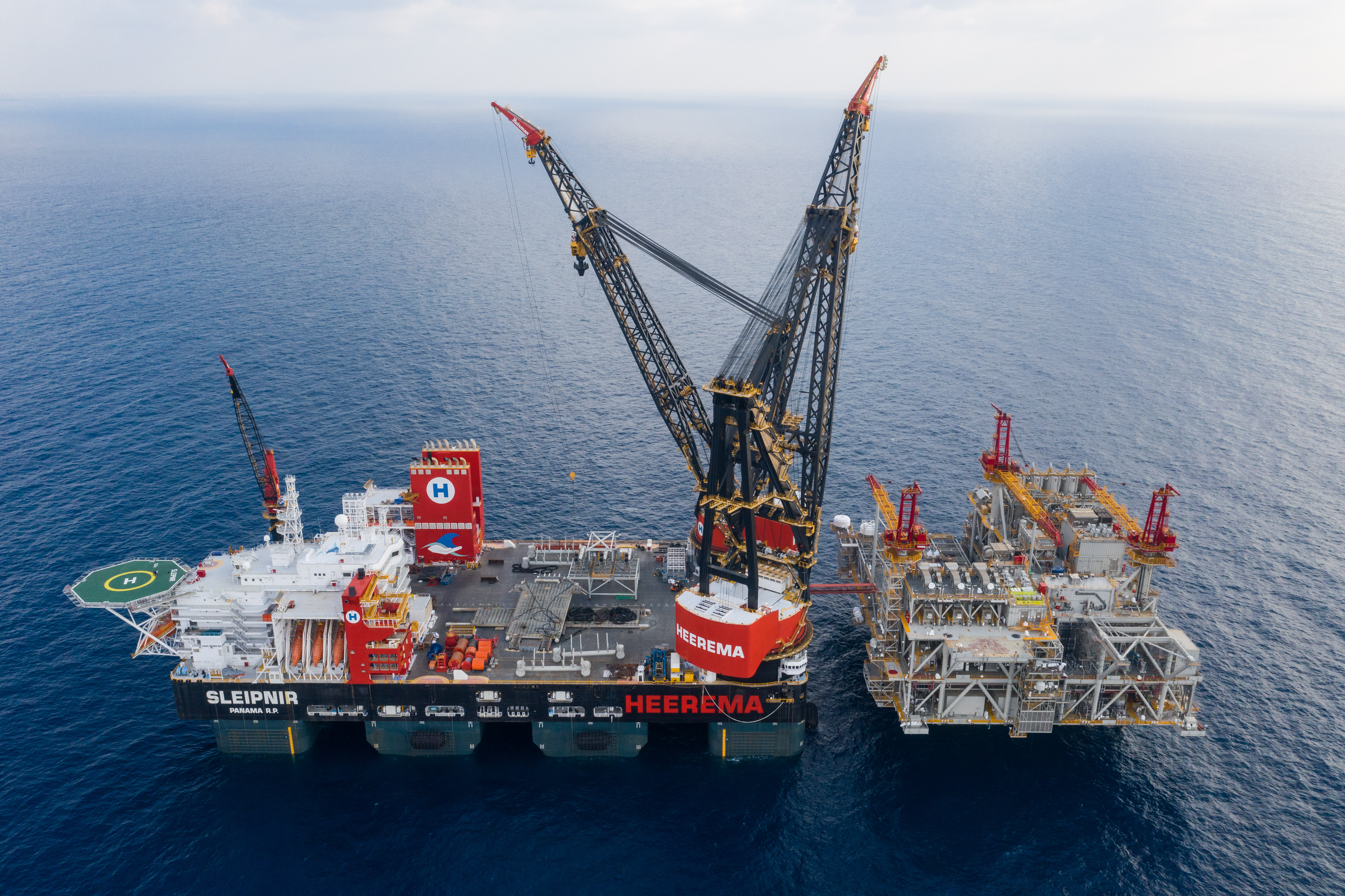
Heerema’s Semi-Submersible Crane Vessel (SSCV) Sleipnir, the world’s largest crane vessel, has successfully completed a 15,300 tonne lift to install the topsides for Noble Energy’s Leviathan development in the Mediterranean.

 
This sets a world record: lifting a module of this weight has never been done by a crane vessel before. Sleipnir installed its two main topsides with a total weight of 24,500 tonnes in less than 20 hours. 
 
The vessel entered service last July. Two revolving cranes can lift up to 20,000 tonnes in tandem. Heerema’s CEO Koos-Jan van Brouwershaven commented about the lift: ‘We are very proud of this achievement. Sleipnir is a unique vessel. It is LNG-powered and thus climate friendly. And our client enjoys the benefits. Because lifting larger modules means less time involved and therefore a smaller budget will suffice for a job.’


Images: 

Is this the future for oil well cement research?

$
0
0

A key part of drilling and tapping new oil wells is the use of specialised cements to line the borehole and prevent collapse and leakage of the hole. To keep these cements from hardening too quickly before they penetrate to the deepest levels of the well, they are mixed with chemicals called retarders that slow down the setting process.

It’s been hard to study the way these retarders work, however, because the process happens at extreme pressures and temperatures that are hard to reproduce at the surface.
Now, researchers at MIT and elsewhere have developed new techniques for observing the setting process in microscopic detail, an advance that they say could lead to the development of new formulations specifically designed for the conditions of a given well location. This could go a long way toward addressing the problems of methane leakage and well collapse that can occur with today’s formulations.

Their findings appear in a paper by MIT Professor Oral Buyukozturk, MIT research scientist Kunal Kupwade-Patil, and eight others at the Aramco Research Centre in Texas and at Oak Ridge National Laboratory (ORNL) in Tennessee.

“There are hundreds of different mixtures of cement currently in use,” said Buyukozturk, who is the George Macomber Professor of Civil and Environmental Engineering at MIT. The new methods developed by this team for observing how these different formulations behave during the setting process “open a new environment for research and innovation in developing these specialised cements,” he added.

The cement used to seal the lining of oil wells often has to set hundreds or even thousands of metres below the surface, under extreme conditions and in the presence of various corrosive chemicals. Studies of retarders have typically been done by removing samples of the cured cement from a well for testing in the lab, but such tests do not reveal the details of the sequence of chemical changes taking place during the curing process.

The new method uses a unique detector setup at Oak Ridge National Laboratory called the Nanoscale Ordered Materials Diffractometer, or NOMAD, which is used to carry out a process called Neutron Pair Distribution Function analysis, or PDF. This technique can examine in situ the distribution of pairs of atoms in the material that mimic realistic conditions that are encountered in a real oil well at depth.

“NOMAD is perfectly suited to study complex structural problems such as understanding hydration in concrete, because of its high flux and the sensitivity of neutrons to light elements such as hydrogen,” said Thomas Proffen of ORNL, a co-author of the paper.


The experiments revealed that the primary mechanism at work in widely used retarder materials is the depletion of calcium ions, a key component in the hardening process, within the setting cement. With fewer calcium ions present, the solidifying process is dramatically slowed down. This knowledge should help experimenters to identify different chemical additives that can produce this same effect.

Images: 

Fuel storage facility expands in Amsterdam

$
0
0

GPS Amsterdam has opened its expanded storage and blending facility for gasoline, gasoline components and biofuels in the Port of Amsterdam, the world’s largest trading and blending hub for gasoline and gasoline components.

 
The company has expanded its class 1 certified storage capacity from 148,500 m3 to 282,500 m3 across 17 tanks as part of an international GPS programme of key asset developments and acquisitions. The expansion marks the latest development in this international strategy and follows major ‘buy and build’ investments at GPS’ Greenfield projects in the UAE and Malaysia.
 
The new storage tanks will create a larger and more bespoke terminal facility offering increased capability and a high degree of flexibility. The expansion will mark the latest achievement in GPS’ strategic partnership with VARO Energy and the Port of Amsterdam. In addition to gasoline, gasoline components and biofuels, the terminal can also handle other commodities to allow the company to meet a growing consumer demand for greater flexibility.
 
As part of its expansion as the terminal, GPS will also develop a rail handling facility, to equip its site with a cost effective and sustainable alternative to road and river transport for a range of its energy and chemical commodities. The development complements the Port of Amsterdam’s sustainability strategy objectives, which endorses the importance of good rail connections to and from the Amsterdam port region and dramatically boost operations efficiency and value for clients.
 
Eric Arnold, CEO at GPS, says “The opening of this facility is an important milestone for GPS. The investment in increased capacity and flexibility which are now built into the Amsterdam terminal reinforces GPS’ commitment to providing customers with world-class assets, while pursuing our global expansion plans. We’re excited by the  possibilities of our expanded site and are committed to additional investments here in Amsterdam that will ensure both GPS and our customers are well positioned to capture future opportunities.”
 

Tags: 
Images: 

Shell side fouling innovation launches demonstrations

$
0
0

Tube Tech International has announced that its multi-million-dollar Shell Side Jet innovation has begun live demonstrations to the open market. The innovation, which is the result of a multi-million-dollar R&D investment, guarantees to remove fouling from the outside heat transfer surface of shell and tube exchangers for the first time.

Developed by Tube Tech International, with R&D funding from the Horizon 2020 programme, via the SME Instrument, Shell Side Jet has been created to meet the demands of the petrochemical market for a solution that can clean in-between shell side tubes. Its makers believe it will be the only technology able to tackle shell side fouling with guaranteed results.

Derek Sumsion, R&D Manager for Tube Tech International, says: “The live demonstrations of our Shell Side Jet solution is a huge milestone for us, prior to the system’s launch in March 2020. We have spent years researching and developing solutions to the industry’s most difficult fouling challenges, and we are proud to be demonstrating this unique service, which we believe is the first of its kind.  

“The technology includes a detection system that is able to indicate bent tubes and severely fouled areas, protecting the asset and ensuring a more precise clean. We are also able to offer the client detailed digital reports that include information such as the distance of baffle plates, location of damaged or broken tubes, volume of fouling, photos of before, during and after the clean, and an intuitive heat map.

“Using this system, we can restore assets to near design thermal efficiency, in turn reducing CO2 emissions and improving productivity, which will ultimately save millions of dollars a year for refineries across the world.”

Images: 

Micro-metering pump for gas odorisation

$
0
0

According to the German Energy Agency (dena), biomethane production in Germany may increase as much as 10 times over – from currently 9 terawatt hours to about 100 – by 2050. What is more, natural gas is the most important energy source for private households and accounts for 44% of the heating market.

Before natural gas or biogas is fed into commercial supply networks, it must have an odorant added to it. Odorants serve as a warning in case of leakage.

Since the last few years have been marked by a trend toward decentralised production, Lewa has added the MAH 4 size to its micro-metering pump portfolio as a proactive measure for meeting the expected increase in demand. The new unit can be used for odorising with mercaptans or tetrahydrothiophene at a throughput rate of up to 12,500Nm³/h. The pump covers the flow range from 200 to 250ml and can be used as a cost-effective solution in accordance with DIN-EN 1333 for gas networks up to PM 16.

“Back in early 2018, we started getting more requests for odorising gas volumes of approximately 12,500Nm³/h, to the point where it just made sense to design a pump specifically for that amount,” says Walter Richter at Lewa. “The right way for us to respond to this trend was to add an intermediate size, the MAH 4, to our hydraulically actuated and solenoid-driven micro-metering pumps from the MAH, MBH and MLM series. The new size meets the requirements for this range exactly.”

The new unit closes the gap between the MAH 3 and the MAH 5 – something that had previously been done using the larger MLM 15 series. However, the stronger stroke solenoid made that design over-dimensioned and less cost-efficient in some cases. Neither the MAH 3 nor the MAH 5 units from the same series were cut out for the job. There was always one of two problems: either they could not manage to pump at the required output of 16 bar, or they could manage a sufficient flow rate at 600ml but were not designed for the necessary discharge pressure.


Images: 

Mildew-resistant coating keeps storage tanks looking better for longer

$
0
0

To enhance efficiencies for asset owners in the oil & gas storage tank segment in the EMEAI region, Sherwin-Williams Protective & Marine Coatings has launched its new epoxy coating offering mildew-resistant corrosion protection with a long-lasting, more aesthetic finish.

The high-solids, high-build, fast-drying polyamide Macropoxy 646MR primer builds on the existing proven Macropoxy 646 technology, offering high chemical and abrasion resistance inside as well as outside of the tank with the added formulation of outstanding mildew resistance.

The new Sherwin-Williams solution keeps tanks and pipelines working more efficiently with a more aesthetic finish than previously available. With low volatile organic compounds (VOCs), application can be performed on site or in shop by brush, roller or airless spray.

“This coating is simple to apply without having to completely remove existing systems, and resists the growth of mildew on the exterior of tanks or external pipelines,” says Michael Harrison from Sherwin-Williams Protective & Marine Coatings.

Designed for use in maintenance, repair or in new construction, Macropoxy 646MR is an ideal durable corrosion protection coating for storage tanks, fixed roofs, floating roofs, vessels and pipelines.

The range of protective lining products offered by Sherwin-Williams is tailormade to each specification, combining exceptional anti-corrosive performance with effective chemical resistance.

Images: 

Protection system for gas pipelines in the UAE

$
0
0

Presenting a recent case study, Chris Todd explains how three types of protection system for gas pipelines were deployed in the UAE

DUSUP (Dubai Supply Authority) recently specified a particular liquid epoxy coating for a buried gas pipeline project in Dubai, UAE. The project was undertaken by the main contractor Global Technologies Projects and Services (GTECH) with help from subcontractors Al Raha Metal Products Factory,  Al Raha Mechanical Equipment and WLL (Arm group of companies).

DUSUP required three solutions for three different types of infrastructure. Having already specified Denso Protal 7200 for the 24in diameter block valves and straight pipe lengths, it asked Denso to provide additional systems for the 2in diameter connecting valves and pipe tie-ins. Winn & Coales’ (Denso) lengthy experience in corrosion prevention enabled it to provide the following solutions.

System 1 (epoxy), for the 24in diameter block valves plus straight pipe sections.

The surface was abrasive blast cleaned to a clean near-white finish, SSC-SP 10/Nace No 2. An appropriate angular grit was used to achieve an anchor profile (63 to 127 micron). Chlorides were removed to an acceptable level of below 3 micro grams per cm2. A coat of Protal 7200 was then spray-applied over the entire area to a minimum of 508 microns and a maximum of 1,270 microns, in accordance with DUSUP’s specification.

System 2 (petrolatum), for the protection of the 2in diameter valves. After a thorough cleaning of the valve surface removing all dust, dirt and loose matter, a coating of Denso Paste was brush-applied over the entire area. This was followed by an application of Densyl Mastic to fill any voids and irregularities, creating a smooth surface for the following tape wrapping. Next, a spiral wrap of Densyl Petrolatum Tape with a 55% overlap was applied over the valve. A final spiral wrap of Denso PVC Outer Wrap with a 55% overlap completed the protection system.

System 3 (bitumen), for the protection of the pipe tie-ins. After the existing coating was profiled to a 20° angle, all dust and sand contaminates were removed. A brushed coat of Denso Primer D was then applied to the pipe area to be protected at a minimum of 150mm either side of the coating interface and allowed to dry. This was then followed by a spiral wrap by hand or pipe wrapping machine of Densopol 60HT Bitumen Tape with a 55% overlap. A final spiral wrap of the Denso PVC Outer Wrap was applied by hand or machine with a 55% overlap to complete the protective system.

New tractor for submerged arc welding

$
0
0

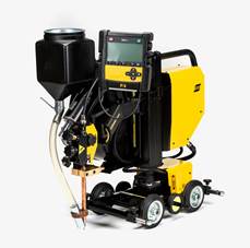
Versotrac’s modularised components can be disassembled into smaller units, hand-carried into confined or remote spaces and then reassembled in minutes. No tools are required.

“This modular tractor system recognises the portability needs of ship, barge, offshore, wind tower and structural steel applications. Versotrac is a truly modular welding tractor, allowing users to take it anywhere without the need for cranes or other lifting devices,” said Magnus Svedlund, Global Product Manager SAW Equipment, ESAB.

The Versotrac can be rebuilt for optimum beam welding positions (including fillet welds in the flat position), comes in four- and three-wheel versions and can be adapted for both inverter-based AC/DC power sources and conventional DC and AC power sources. A new wire spool handling system detaches for easier transportation and more ergonomic loading of wire spools, while steering handles let operators easily change weld point position.

Quick-connect welding head

ESAB further enhanced the modular design of the Versotrac with its EWH 1000 welding head and EAC 10 controller, both of which detach. Their associated quick connectors and automatic detection/setup by the controller let users switch between the SAW, GMAW and Gouging processes in seconds.

The Versoarc EWH 1000 welding head incorporates a wire feed system that can weld with single wires up to 5mm and up to 1000A @ 100% duty cycle. For higher productivity (20+ kg/hr deposition), the Versoarc EWH 1000 can be used with twin wire process. A closed-loop encoder control system ensures precise wire feed speed control.        

It uses the entirely new and intuitive EAC 10 controller. Its simplified interface includes functions users need for tractor-based and other light-automation applications, making more room on the display for important functions like real-time, on-screen heat input to monitor and control weld quality. The EAC 10 pendant detaches from the base control unit so operators can work in a comfortable position and change settings from a distance. The controller works with all current ESAB submerged arc welding power sources, as well as most analog power sources on the market.


Protecting pipelines with cathodic protection

$
0
0

Over the past three decades, corrosion problems have reduced the life expectancy of the pipe system down to only a few years. In the USA alone, corrosion costs the industry more than a billion dollars a year.

What causes corrosion in pipelines

Pipeline corrosion is a natural occurrence. Pipe material and essential properties deteriorate over time. Corrosion occurs due to electrochemical reactions of pipeline materials with their environment. You can find corrosion on the inside as well as outside surfaces. Like any other natural hazard, pipeline corrosion can cause a life-threatening failure. It can also cause expensive damage to the pipeline and related systems.

Cathodic protection against corrosion

You can shield steel piping with cathodic protection to prevent corrosion. This technique reduces the corrosion of the metal surface. It does so by making the surface the cathode of an electrochemical cell. This cathodic protection system works by applying a small current to the pipeline. The technicians apply the current to the pipelines via units known as transformer-rectifiers, which convert AC electricity into DC. The plant uses this electricity to lower the ‘energy’ of the pipeline.

The impressed cathodic protection shields some piping against corrosion. This type needs a non-conductive barrier between the process piping and the instrument. The barrier protects it from the effects of electrical current. This measure, in turn, protects expensive electronics.

Recommended dielectric isolation kits

AS-Schneider recommends using a dielectric isolation kit as a non-conductive barrier. This kit is for installation on the inlet flange connection of the manifold. It goes between the stabilised connector and the manifold.

The firm has designed dielectric isolation kits to maintain the integrity of the pipeline. They also ensure the reliability of the piping system through safety and corrosion protection. Dielectric isolation kits provide an effective seal and electrical isolation of flanges. Eliminating metal to metal contact halts static current. In this way, electronic harm to the instrument is prevented.

Looking back a few years, when the firm was developing the dielectric isolation kit, there was a big challenge. That challenge was how to get a reliable, leak-tight connection for 6,000 psi (414 bar). The connection had to be without an encapsulated gasket. The company also had to tighten the bolting against a non-conductive soft plastic material. But it never backs down from a challenge: “The challenge is one of the reasons why developing products is so much fun and is always exciting for me,” explains Markus Häffner, director of Design and Development, AS-Schneider.

When it came to requirements for the dielectric isolation kit, in the beginning, this development did not look like a big challenge. However, in the end, the team had to make many tests to have a safe and reliable product. Why? The task seemed to be quite easy, but so often the devil is in the details. In this case, the requirements were:

  • Pressure of 6,000 psi (414 bar)
  • Rating: 2,500 VDC/Resistance: 5 Meg Ohms
  • Temperature: 176°F (80°C)

Dielectric isolation kits development process

For a leak-tight sealing system up to 6,000 psi (414 bar), it had to tighten the bolts with a defined torque. The plastic also had to absorb the forces resulting from this torque. Additionally, the sleeves become very soft when heated to a temperature of 176°F (80°C) and tend to creep. This creeping causes the bolt tension and thus the compression of the seal ring to decrease. At this point, leakage can occur.

To achieve the goal, the team conducted detailed investigations of the gasket geometry, extensive testing of the composition of different plastic materials. It even tested different contents of glass fibre for its reinforced plastics.

The dielectric isolation kit is an essential part of the company’s Direct Mount System, as it enables close coupling of electronic flow measurement devices to an orifice fitting. AS-Schneider designed these systems for close coupling in a safe, efficient manner. They cut or reduce the effects of gauge line error.

The Pipeline Gas Compressor Research Council and Southwest Research ran a recent study. It looked at pulsation created by regulators and flow control valves. The team also researched compressors and some piping configurations. They found that pulsation may create undesirable levels of square root error. It also creates gauge line error. Pulsation at the orifice meter is a significant source of lost natural gas. These errors cause huge economic gains or losses. They affect both the buyer and seller in a natural gas pipeline system.

The research made some conclusions about transmitters and electronic flow measurement devices. It found they should use equal length, large orifice constant diameter gauge lines. They should also use multi-turn valves to protect electronics from pressure spikes. These should be close coupled to the orifice taps.

The AS-Schneider system minimises or eliminates gauge line error, and it’s easy to install. Also, it’s available in both vertical and horizontal to vertical configurations.

Leak-free measurement installation

AS-Schneider has developed the so-called Schneider DirectMount System – SDMS for short. By using the SDMS, operators reduce the installation costs significantly. There’s no need to manufacture and install tube runs, fittings, and expensive pipe stands. The SDMS reduces potential leak points associated with NPT connection. The solution also provides a safe, compact, leak-free measurement installation. The internal porting promotes self-draining of condensates and liquids to reduce freezing issues.

It uses the IEC 61518 system, which meets the recommendations of the American Petroleum Institute. The Gas Processors Association and the American Gas Association have also approved it.

From rust to robust - Welding Automation for corrosion protection

$
0
0

The efficient prevention and minimisation of corrosion-induced deterioration in distillation columns is a key aspect in helping refineries to remain highly productive and competitive. One of the world’s top integrated energy companies was experiencing corrosion issues on several units in its refinery complex in Spain. Sulzer’s automated weld overlay capabilities provided an economical and efficient solution to de-bottleneck the different columns and extend their service lives.

The refinery complex is one of the five largest in Spain. The plant processes crude oil to obtain a broad range of chemicals, such as methyl methacrylate and polypropylene.

When the refinery noticed extensive corrosion within the column shells of three main separation towers, it sought to investigate the issue and protect its plant from costly shutdowns or lengthy periods of suspended production.

The initial inspection revealed that the column shells of the atmospheric distillation unit (ADU), the vacuum distillation unit (VDU) and a third fractionator were experiencing corrosion and erosion responsible for cracks, pitting and material losses. In particular, the column showing higher levels of corrosion was the VDU.

The structure of the VDU consisted of one wash bed and three pump-around circuits for the recovery of HVGO (heavy vacuum gas oil), LVGO (light vacuum gas oil) and LLVGO (light light vacuum gas oil or very light vacuum gas oil). The tower had an internal diameter of 9.15m and its shell was made of carbon steel coupled with a 3mm bonded plate to prevent corrosion. Over time, the plate started to corrode and lost its ability to protect the underlying column shell. Based on the visible damage present on the bonded plate, the surface area of the damage was estimated around 65m2.

To repair and upgrade its columns, the refinery turned to Sulzer, whose Tower Field Service group has been supporting the company in the past with routine maintenance activities and field services.

The solution - Welding automation

Sulzer’s expert team performed an in-depth visual inspection. To do so, the bonded plate was removed to expose the carbon steel shell. This examination revealed that the extent of column shell corrosion was almost double that of the initial estimate, covering approximately 110m2.

In these situations, refineries are often faced with the choice between replacing the entire column or part of it, which is costly and time-consuming, or applying thermal-spray coatings that can prevent column corrosion only for a limited time.

Sulzer offered a third, more time-efficient, economical and long-lasting option: weld overlay. By using this in situ process, it is possible to cover large column surfaces with corrosion-resistant alloys. The company is highly experienced in this technique and has developed an advanced, fully automated weld overlay equipment to support its operations.

This machine consists of a carriage travelling along a laser-levelled track system fixed to the column shell wall. On the carriage, a robotic index arm moves the welding torch and the oscillator to create weld beads. All the relevant process parameters, such as carriage speed or bead thickness, are controlled by a programmable logic controller (PLC), with which human operators can communicate by means of human-machine interfaces (HMIs). One single PLC can monitor multiple welding machines following the same instructions.

The automated process can quickly perform welding with high accuracy. As a result, customers can benefit from a high-quality and consistent process as well as short downtime. In this case, Sulzer could complete the overlay of the 110m2 VDU corroded surface in the time allocated to 65m2.

To reduce the likelihood of future corrosion, the VDU column shell was overlaid with layers of austenitic stainless steel type 316 alloy, which is widely used in welding processes to avoid carbide precipitation. In addition, the presence of molybdenum and nickel makes the alloy suitable for applications in harsh conditions.

Comprehensive corrosion protection

In addition to repairing the VDU column shell, Sulzer also performed weld overlay on the corroded surfaces of the other two towers, namely the ADU and the third fractionator. Also, column internals, such as trays and packings, were replaced to further improve the performance of the entire oil distillation system.

The weld overlay process was performed in two weeks, while the entire revamp was concluded in 25 days, without any delays despite the discovery of larger corroded areas within the VDU, increasing the required weld overlay to almost double that of the originally estimated area.

Since the revamp, the refinery has operated smoothly at full capacity and the solution from Sulzer could also support the shift towards different crudes without affecting the columns’ corrosion resistance. The customer was so pleased with the work that it offered to provide a positive reference to any potential customers of Sulzer.

Andrew Petticrew at Sulzer Tower Field Services, comments: “The ability of our experts to resolve unexpected issues, coupled with our automated weld overlay capabilities, were crucial to ensure the timely repair of the corroded column shells. In addition, the customer could benefit from a one-stop-shop for the revamp project, as we took care of dismantling the existing column internals, as well as the manufacture and installation of new ones.” 

The impact of COVID-19 on the oil industry

$
0
0

After a rocky few years, the oil industry is forecasted to see a decline in oil demand growth for the first time since 2009. The IEA is expecting the first quarter of 2020 to see the demand decrease by 2.5 million barrels per day year-on-year.

March Oil Market Report summary

The IEA Oil Market Report provides authoritative data, forecasting and analysis of the global oil market. March sees their latest report which, of course, discusses the impact COVID-19 has had on the market.

As coronavirus spreads across the globe, the IEA is estimating a fall in demand by 90 kb/d year-on-year. In 1Q20 alone, global demand has decreased by 2.5 mb/d. The assumption is that we will see demand return in 2H20 to almost normal.

In addition to a fall in global oil demand, the IEA reported a decrease in global oil supply in February of 580 kb/d and estimates that 2020 global refining throughput will fall below 2017 levels for a second consecutive year. The decrease in throughput is directly associated with coronavirus, due to the decreased demand in transport fuel.

January saw OECD industry stocks increase by 27.8 mb, reaching 2930 mb. As promising as this looks, it was actually due to product inventory building offsetting counter-seasonal draws of crude stocks.

Coronavirus and the oil market

On March 23rd, the World Health Organisation confirmed that cases of coronavirus have surpassed 300,000. The impact of COVID-19 on the oil industry is predicted to result in the first full year decline in over ten years.

China accounted for over 80% of oil demand growth globally which has played a role in this decrease. While data collection has not yet been completed, the first quarter of 2020 has seen a marked decline in commercial and industrial activity points and transport. This has resulted in global oil demand dropping by 2.5 mb/d comparative to the same period last year.

The IEA Oil Market Report states that the oil market outlook will be dependent on government efforts to contain the outbreak, the success of any actions taken and the ‘lingering impact’ the crisis has on economic activity. In light of this, the IEA has had to propose base case alternatives, including both a pessimistic and optimistic outlook depending on the continued impact of coronavirus, which can be found in the report.

The IEA’s pessimistic low case

This case expects countries that have already been impacted by the virus will see a slow recovery as the pandemic continues to spread. It takes into consideration that efforts to control the propagation of the virus will take longer, while oil demand in China will ease more slowly throughout March.

The third quarter of 2020 will see European oil demand continuing to be subdued, with US demand growing at a reduced pace. The IEA predicts that in 2020, oil demand could potentially decline by 730,000 barrels per day in this case.

The IEA’s optimistic high case

The optimising high case is based on the assumption that China can bring the outbreak swiftly under control and that more severe contagion is limited to a few countries, with Europe and North America seeing no serious impact. In this outlook, government containment does not require strong measures and transport use ‘remains closer to normal’. Predictions by the IEA, in this case, see 2020 oil demand growing by 480,000 barrels each day.

The World Health Organisation has reported that the coronavirus pandemic is accelerating. This, along with government action, means the full impact of coronavirus on the oil industry is yet to be seen.

Oil tanker successfully tests marine biofuel

$
0
0

The 49,646 deadweight tonne (dwt) MR tanker received the first delivery of Bio Fuel Oil during its recent call at the Port of Rotterdam. The fuel, which GoodFuels launched in 2018, reduces greenhouse gas emissions by 83% and substantially reduces SOx emissions. 

The trial was completed on the Stena Immortal as she ran on a typical commercial operation. During the trial, BFO was tested in tanks, storage and as it was burned in the engines, the fuel proved to be a technically compliant alternative to the fossil default for oceangoing tanker vessels.

The success of this trial underlines sustainable marine biofuel's position within the marine mix, and helps owners and operators to future-proof against current and impending regulations. As the trial was conducted with 100% biofuel, it also shows that low-carbon shipping doesn't have to be decades away but viable also on the shorter term if industry leaders work together to push the development.

Because it substantially reduces CO2 and SOx emissions, GoodFuels' Bio Fuel Oil ensures compliance with the International Maritime Organisation's (IMO) 2020 Sulphur Cap, Greenhouse Gas (GHG) reduction requirements and upcoming regulations to reduce carbon intensity from shipping.

"We like to show the industry that we can start reducing the carbon footprint of shipping here and now while maintaining highest quality technical and commercial operations. The Stena Immortal performed very well running on the biofuel while continuing to deliver according to our customers' needs without any disruption", said Erik Hånell, President and CEO Stena Bulk.

"The industry needs pioneers willing to collaborate, share knowledge and push the development towards more sustainable shipping. We're happy to collaborate with GoodFuels in this test to take on that mission and encourage others to join us. We are of course open and have a willingness to drive and take part of this development together with stakeholders in this industry,” Hånell continued.

"We are delighted this test with Stena Bulk was a success and want to thank them for joining us in our mission to develop a carbon-busting solution that is scalable, truly sustainable, technically compliant and, crucially, affordable", Dirk Kronemeijer, CEO, GoodFuels Marine, commented on the successful trial.

"For the past five years, we have focused on realising the widescale use of sustainable marine biofuel, which has enabled us to continue to develop biofuels as a true solution to the market's problems. This marks yet another a crucial move towards offering the shipping industry a credible near-zero carbon alternative to HFO and VLSFO."  

Stena Bulk and GoodFuels Marine will continue working together to gain more experience and scale the usage of Bio Fuel Oil as an alternative to conventional fossil-based fuel. 

The fuel is sustainably sourced and completely derived from forest residues and waste oil products. It is verified by an independent sustainability board of leading academics and NGOs. 


New partnership aims to deliver TCP risers

$
0
0

Oilfield technology firm Airborne Oil & Gas and engineering company Símeros Technologies have signed an agreement which aims to deliver the first qualified Thermoplastic Composite Pipe (TCP) risers in the deepwater region Brazil.

 
Last year, Airborne Oil & Gas commenced its TCP riser qualification program. The technology is believed to be a world first for fully bonded, free hanging composite risers with the aim of providing a disruptive new riser pipe technology for operators with international deepwater applications.
 
The program is receiving funding from a major operator in the region and is aimed at qualifying the TCP riser for dynamic deepwater applications, including for pre-salt and highly corrosive conditions, against an ambitious timescale.
 
The TCP flowlines and risers developed by Airborne Oil & Gas can be installed by existing flex-lay and reel-lay vessels and be installed in the flexible and cost effective free hanging catenary mode. “Installed in free hanging catenary configuration, our TCP Riser provides the opportunity for significant savings on typical FPSO development, through faster installation and avoiding the need to use buoyancy modules”, said Oliver Kassam, Airborne Oil & Gas CEO.

Read about bearing requirements for risers here.


Viewing all 299 articles
Browse latest View live