Quantcast
Channel: Engineer Live - Production/Processing
Viewing all 299 articles
Browse latest View live

Patented thermoplastic aimed at oil & gas applications

$
0
0

Greene Tweed has launched Arlon 3000 XT, a new thermoplastic for extreme conditions in oil and gas applications.

In dynamic mechanical analysis it demonstrated a glass transition temperature 35°F higher than PEEK, and provided superior mechanical property retention from 350°F to 600°F. In extrusion testing, it outperformed both virgin and filled grades of PEEK and PEKEKK.

Arlon 3000 XT provides improved volume resistivity 30 times that of PEK at 400°F and dielectric strength, measured at 730 V/mil using a 40 mm thick sample in ASTM D149 testing. In addition, it has 1.5 to 6 times higher mechanical properties compared to PEEK in tensile, compressive, flexural and shear tests at a test range of 392°F to 500°F, which provides the support typically provided by a metal element.

It is capable of withstanding all common oilfield chemistries, and is appropriate for use in back-up rings, v-rings, electrical connectors and seal assemblies.


Heavylift crane shaves a month off Iraqi refinery project

$
0
0

ALE mobilised a heavylift crane to install three tank roofs, saving over a month from the schedule of a section of the Karbala Refinery Project in Iraq. The new facility is expected to have a refinery capacity of 140,000 barrels of crude oil per day and this operation had a tight deadline to keep the $6.04bn project on track.

The tank roofs had been built inside the tanks and the client initially planned to raise them by air. ALE had previously completed a large scope of work on the project of more than 350 lifts of refinery components, so the client had faith in its expertise. ALE’s ability to quickly reconfigure one of the largest-ever capacity cranes in Iraq presented an alternative option that would save time and enable the client to proceed to its next phase ahead of schedule.

The early involvement of ALE saved costs on the operation as the client didn’t have to purchase heavy duty turnbuckles or additional lifting tackle. ALE worked closely with the client during the design of the lifting tackle arrangement for each roofs’ 20 lifting points. ALE provided recommendations for the client’s design and fabrication of the specialist lifting device that would ensure equal loading of all slings.

Additional time was saved on the operation as, following a lifting study, ALE was able to perform the lifts from only two crane positions instead of three. Due to the high temperatures on site, movement times were limited, but the team’s experience enabled them to reduce the operation from 21 to 15 days.

ALE used a 1,600t capacity crawler crane to hoist each roof, weighing 209t and measuring 53m in diameter. Once at the required height, they were welded in place.

The Karbala facility was commissioned to help fulfil Iraq’s growing domestic demand, as well as assisting in the country’s transition to become a net exporter of oil products. Production at the refinery is expected to begin in 2022.

Read about ALE’s recent Russian success here.


How To Prevent Pipeline Theft

$
0
0

Pipeline theft is a serious global problem and one that has been on the rise for the past few years. In terms of pipeline integrity, thefts are one of the largest risks that can be hard to prevent without strategic focus. The events in Mexico earlier this year demonstrated the risks thieves will take and the ultimate price some people will suffer as a result. Harry Smith explains how smart technology can help to prevent future thefts.

However, pipeline theft is not restricted to Central and Latin America but extends worldwide, with occurrences in Nigeria, Indonesia and China. In Europe, pipeline thefts have also risen, with incidences found in Eastern and Southern Europe and in the UK. Theft was designated so serious in the UK that the National Crime Agency became involved. The challenge to operators and law enforcement is that there is no single cause of thefts – a wide range of factors including social, economic, political and legal apply. Although some thefts are clearly organised for criminal gain, many are driven by often the most basic of needs, such as obtaining fuel for heating and cooking. It can be these small, ad hoc thefts that can have the worst consequences.

How Do Pipeline Thieves Operate?

Thieves are becoming more sophisticated and organised, using specialist equipment such as commercial-grade welding machines, calibrated measuring instruments, night vision goggles and vans with modified suspension or exit holes built into the floor of the vehicles. Thieves will also sample product to decide if it is the right product to steal.

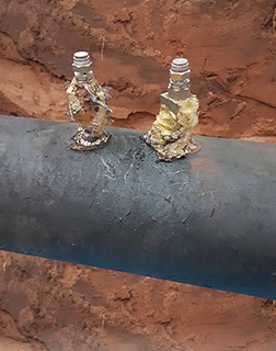
From a technical perspective thieves will deploy several tactics, including: pre-install the tapping point, hose, associated valves and equipment before a pipeline is commissioned; select remote and well-hidden sites such as abandoned buildings such as farms and old factories; bury and cover the hosepipe and all other devices underground. Other tactics include opening the tapping point valves very slowly to generate small pressure change over a long time (known as the patient thieves), and maintaining the theft rate below flow meter repeatability level, e.g. 0.1% of pipeline throughput.

Adding to the challenging in detecting thieves is that they often carry out the activities at night. They frequently steal small volumes each time or inject water into the pipeline while taking oil out. It’s not uncommon for thieves to conduct thefts at multiple locations along the same pipeline.

Thieves increasingly use dangerous techniques, including angle grinding and plastic equipment. At worst, thieves have driven stakes into pipelines and used rags to reduce the flow out of the pipeline.

All of these different tactics make it difficult for pipeline companies to detect and locate thefts quickly and accurately. Although leak detection methods have previously been used for theft detection, a more focused approach is required.

The application of the negative pressure wave, statistical volume balance methods is extremely beneficial for theft detection, with the use of offline analysis and further instrumentation. As every pipeline is different, a ‘one size fits all’ approach is not suitable, however: each technology has its advantages and can often be combined to provide an integrated approach. Furthermore, non-intrusive pressure sensors with remote radio and cellular communications and battery-powered data logging can provide additional accuracy to support GPS location and offline analysis.

Pipeline Theft Detection Solutions 

Avoiding detection is a key target when thieves are going to commence an operation to extract the product from a pipeline. This approach differs from pipeline leaks in several ways: a small amount of product is stolen (ranging from 10 to 3,000 litres); theft flow rate can be less than 0.1%; theft events last for less than one hour usually although occasionally a theft continues unchecked; and the changes in pressure are very small when the tapping point is opened/closed at the end of a long hosepipe.

With these unique characteristics the main requirements of theft detection are: sensitivity (detecting the small product withdrawal); accuracy (locating the tapping point as accurately as possible); and response time (detecting the product withdrawals as quickly as possible). 

Different leak detection technologies can be adapted to meet the above requirements. The main theft detection options are negative pressure wave, statistical volume balance and theft service approach.

Negative Pressure Wave

This technology relies on high-speed analogue pressure sensor readings to identify whether a leak/theft has occurred on the pipeline. The system acquires and analyses the pressure data at a frequency much higher than the typical five-second SCADA rate, capturing data at 60 samples a second. Specialised equipment is thus needed to acquire data at such high frequency.

The main advantages of this system are: accurate leak location within metres of the actual location; short detection time for all leak sizes; and high sensitivity provided through the 60hz sample rate. These are the key features in effectively detecting theft events in all operational conditions.

Statistical Volume Balance

This type of leak detection technology relies on the pressure and flow measurements taken from a pipeline. It uses the existing instrumentation and connects via existing SCADA, PLC or remote terminal unit (RTU) systems. This system monitors the difference between the inlet and outlet flow corrected by the inventory change. This is also referred to as the “corrected flow difference” to determine whether the pipeline is in a leak condition.

The statistical hypothesis testing method is known as the sequential probability ratio test (SPRT). It is applied to the corrected flow difference to decide if the probability of a leak has increased.

The main advantages of this system are a low false alarm rate, the ability to detect leaks under steady-state, transient and shut-in conditions, and accurate leak size estimate. Leak location accuracy is improved through higher data sample rates.

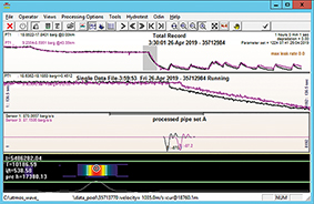
Since the theft rate is usually below the flow meter accuracy and repeatability level, it is difficult for this technology to detect small thefts under running conditions unless false alarms are accepted. The system includes an additional theft module for detecting thefts during shut-in conditions to maintain reliability for both leak and theft detection. The figure on the following page shows an example of it working.

Protecting The Future Of Pipelines

Thefts are not a constant and can fluctuate. Tapping points are often left for years. In the UK a recent tapping point was located that was likely installed as far back as 2015 and left dormant until earlier this year.

When the volume of thefts along a pipeline reduce, it becomes necessary to lower the minimum leak size to be detected. However, in doing this, it can result in increased false alarms as the identified flow and pressure are mostly below the instrument repeatability and process noise level.

An offline service can be offered to pipeline firms. Combining technology with an offline service can provide improved leak location accuracy and sensitivity without unnecessary false alarms.

Deployment of portable and fixed hardware with software solutions allows offline data analysis by an experienced engineer. Through this service, an engineer’s ability to interpret data helps theft to be located down to a few metres, using pressure data collected at 60Hz sample rate and sent to a central location via a cloud-based service.

The data is then filtered to present only the relevant information required and the locations of the illicit tapping points are reported to the pipeline operators.

It is well documented that online leak and theft detection systems must find a balance between sensitivity and false alarms. Some leak detection systems can detect leaks as small as 0.5% of nominal flow-rate without the issue of false alarms. However, this becomes an issue as most theft events are less than 0.3% of the nominal flow-rate. The capability to analyse the data offline has allowed the location and detection of theft to within 5m for thefts as small as 0.1% of the nominal flow-rate in static and running conditions.

Combining a detected theft service with a single or multiple online leak detection system allows for a more reliable leak detection system with the ability to effectively deal with all types of theft events. In the past two years, this combination of negative pressure wave, statistical volume balance and offline analysis has enabled one supplier to successfully detect and locate over 300 tapping points for its clients.


Sleipnir successfully completes 15,300 tonne lift

$
0
0

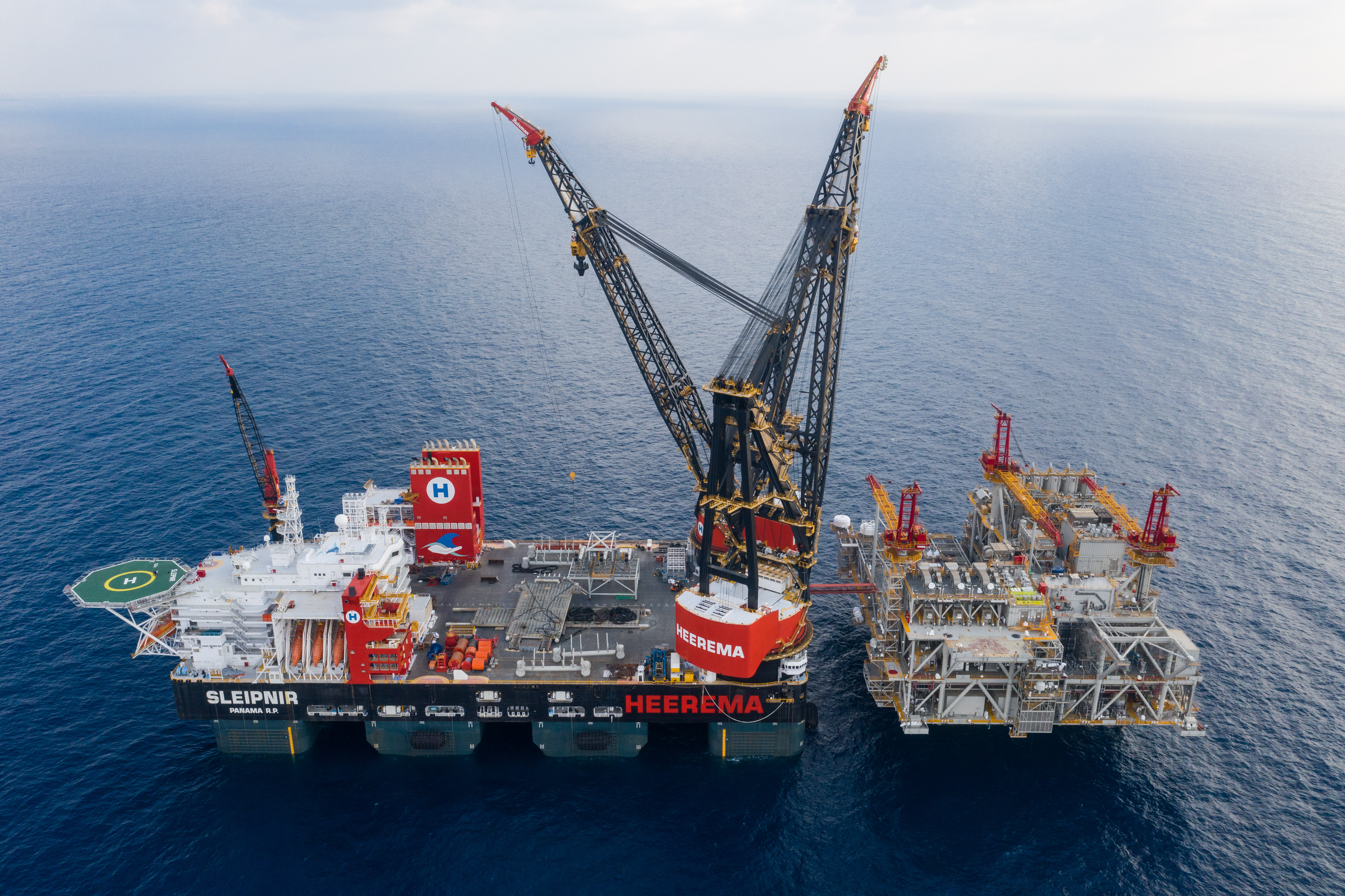
Heerema’s Semi-Submersible Crane Vessel (SSCV) Sleipnir, the world’s largest crane vessel, has successfully completed a 15,300 tonne lift to install the topsides for Noble Energy’s Leviathan development in the Mediterranean.

 
This sets a world record: lifting a module of this weight has never been done by a crane vessel before. Sleipnir installed its two main topsides with a total weight of 24,500 tonnes in less than 20 hours. 
 
The vessel entered service last July. Two revolving cranes can lift up to 20,000 tonnes in tandem. Heerema’s CEO Koos-Jan van Brouwershaven commented about the lift: ‘We are very proud of this achievement. Sleipnir is a unique vessel. It is LNG-powered and thus climate friendly. And our client enjoys the benefits. Because lifting larger modules means less time involved and therefore a smaller budget will suffice for a job.’


Is this the future for oil well cement research?

$
0
0

A key part of drilling and tapping new oil wells is the use of specialised cements to line the borehole and prevent collapse and leakage of the hole. To keep these cements from hardening too quickly before they penetrate to the deepest levels of the well, they are mixed with chemicals called retarders that slow down the setting process.

It’s been hard to study the way these retarders work, however, because the process happens at extreme pressures and temperatures that are hard to reproduce at the surface.
Now, researchers at MIT and elsewhere have developed new techniques for observing the setting process in microscopic detail, an advance that they say could lead to the development of new formulations specifically designed for the conditions of a given well location. This could go a long way toward addressing the problems of methane leakage and well collapse that can occur with today’s formulations.

Their findings appear in a paper by MIT Professor Oral Buyukozturk, MIT research scientist Kunal Kupwade-Patil, and eight others at the Aramco Research Centre in Texas and at Oak Ridge National Laboratory (ORNL) in Tennessee.

“There are hundreds of different mixtures of cement currently in use,” said Buyukozturk, who is the George Macomber Professor of Civil and Environmental Engineering at MIT. The new methods developed by this team for observing how these different formulations behave during the setting process “open a new environment for research and innovation in developing these specialised cements,” he added.

The cement used to seal the lining of oil wells often has to set hundreds or even thousands of metres below the surface, under extreme conditions and in the presence of various corrosive chemicals. Studies of retarders have typically been done by removing samples of the cured cement from a well for testing in the lab, but such tests do not reveal the details of the sequence of chemical changes taking place during the curing process.

The new method uses a unique detector setup at Oak Ridge National Laboratory called the Nanoscale Ordered Materials Diffractometer, or NOMAD, which is used to carry out a process called Neutron Pair Distribution Function analysis, or PDF. This technique can examine in situ the distribution of pairs of atoms in the material that mimic realistic conditions that are encountered in a real oil well at depth.

“NOMAD is perfectly suited to study complex structural problems such as understanding hydration in concrete, because of its high flux and the sensitivity of neutrons to light elements such as hydrogen,” said Thomas Proffen of ORNL, a co-author of the paper.


The experiments revealed that the primary mechanism at work in widely used retarder materials is the depletion of calcium ions, a key component in the hardening process, within the setting cement. With fewer calcium ions present, the solidifying process is dramatically slowed down. This knowledge should help experimenters to identify different chemical additives that can produce this same effect.

Fuel storage facility expands in Amsterdam

$
0
0

GPS Amsterdam has opened its expanded storage and blending facility for gasoline, gasoline components and biofuels in the Port of Amsterdam, the world’s largest trading and blending hub for gasoline and gasoline components.

 
The company has expanded its class 1 certified storage capacity from 148,500 m3 to 282,500 m3 across 17 tanks as part of an international GPS programme of key asset developments and acquisitions. The expansion marks the latest development in this international strategy and follows major ‘buy and build’ investments at GPS’ Greenfield projects in the UAE and Malaysia.
 
The new storage tanks will create a larger and more bespoke terminal facility offering increased capability and a high degree of flexibility. The expansion will mark the latest achievement in GPS’ strategic partnership with VARO Energy and the Port of Amsterdam. In addition to gasoline, gasoline components and biofuels, the terminal can also handle other commodities to allow the company to meet a growing consumer demand for greater flexibility.
 
As part of its expansion as the terminal, GPS will also develop a rail handling facility, to equip its site with a cost effective and sustainable alternative to road and river transport for a range of its energy and chemical commodities. The development complements the Port of Amsterdam’s sustainability strategy objectives, which endorses the importance of good rail connections to and from the Amsterdam port region and dramatically boost operations efficiency and value for clients.
 
Eric Arnold, CEO at GPS, says “The opening of this facility is an important milestone for GPS. The investment in increased capacity and flexibility which are now built into the Amsterdam terminal reinforces GPS’ commitment to providing customers with world-class assets, while pursuing our global expansion plans. We’re excited by the  possibilities of our expanded site and are committed to additional investments here in Amsterdam that will ensure both GPS and our customers are well positioned to capture future opportunities.”
 

Protecting pipelines with cathodic protection

$
0
0

Over the past three decades, corrosion problems have reduced the life expectancy of the pipe system down to only a few years. In the USA alone, corrosion costs the industry more than a billion dollars a year.

What causes corrosion in pipelines

Pipeline corrosion is a natural occurrence. Pipe material and essential properties deteriorate over time. Corrosion occurs due to electrochemical reactions of pipeline materials with their environment. You can find corrosion on the inside as well as outside surfaces. Like any other natural hazard, pipeline corrosion can cause a life-threatening failure. It can also cause expensive damage to the pipeline and related systems.

Cathodic protection against corrosion

You can shield steel piping with cathodic protection to prevent corrosion. This technique reduces the corrosion of the metal surface. It does so by making the surface the cathode of an electrochemical cell. This cathodic protection system works by applying a small current to the pipeline. The technicians apply the current to the pipelines via units known as transformer-rectifiers, which convert AC electricity into DC. The plant uses this electricity to lower the ‘energy’ of the pipeline.

The impressed cathodic protection shields some piping against corrosion. This type needs a non-conductive barrier between the process piping and the instrument. The barrier protects it from the effects of electrical current. This measure, in turn, protects expensive electronics.

Recommended dielectric isolation kits

AS-Schneider recommends using a dielectric isolation kit as a non-conductive barrier. This kit is for installation on the inlet flange connection of the manifold. It goes between the stabilised connector and the manifold.

The firm has designed dielectric isolation kits to maintain the integrity of the pipeline. They also ensure the reliability of the piping system through safety and corrosion protection. Dielectric isolation kits provide an effective seal and electrical isolation of flanges. Eliminating metal to metal contact halts static current. In this way, electronic harm to the instrument is prevented.

Looking back a few years, when the firm was developing the dielectric isolation kit, there was a big challenge. That challenge was how to get a reliable, leak-tight connection for 6,000 psi (414 bar). The connection had to be without an encapsulated gasket. The company also had to tighten the bolting against a non-conductive soft plastic material. But it never backs down from a challenge: “The challenge is one of the reasons why developing products is so much fun and is always exciting for me,” explains Markus Häffner, director of Design and Development, AS-Schneider.

When it came to requirements for the dielectric isolation kit, in the beginning, this development did not look like a big challenge. However, in the end, the team had to make many tests to have a safe and reliable product. Why? The task seemed to be quite easy, but so often the devil is in the details. In this case, the requirements were:

  • Pressure of 6,000 psi (414 bar)
  • Rating: 2,500 VDC/Resistance: 5 Meg Ohms
  • Temperature: 176°F (80°C)

Dielectric isolation kits development process

For a leak-tight sealing system up to 6,000 psi (414 bar), it had to tighten the bolts with a defined torque. The plastic also had to absorb the forces resulting from this torque. Additionally, the sleeves become very soft when heated to a temperature of 176°F (80°C) and tend to creep. This creeping causes the bolt tension and thus the compression of the seal ring to decrease. At this point, leakage can occur.

To achieve the goal, the team conducted detailed investigations of the gasket geometry, extensive testing of the composition of different plastic materials. It even tested different contents of glass fibre for its reinforced plastics.

The dielectric isolation kit is an essential part of the company’s Direct Mount System, as it enables close coupling of electronic flow measurement devices to an orifice fitting. AS-Schneider designed these systems for close coupling in a safe, efficient manner. They cut or reduce the effects of gauge line error.

The Pipeline Gas Compressor Research Council and Southwest Research ran a recent study. It looked at pulsation created by regulators and flow control valves. The team also researched compressors and some piping configurations. They found that pulsation may create undesirable levels of square root error. It also creates gauge line error. Pulsation at the orifice meter is a significant source of lost natural gas. These errors cause huge economic gains or losses. They affect both the buyer and seller in a natural gas pipeline system.

The research made some conclusions about transmitters and electronic flow measurement devices. It found they should use equal length, large orifice constant diameter gauge lines. They should also use multi-turn valves to protect electronics from pressure spikes. These should be close coupled to the orifice taps.

The AS-Schneider system minimises or eliminates gauge line error, and it’s easy to install. Also, it’s available in both vertical and horizontal to vertical configurations.

Leak-free measurement installation

AS-Schneider has developed the so-called Schneider DirectMount System – SDMS for short. By using the SDMS, operators reduce the installation costs significantly. There’s no need to manufacture and install tube runs, fittings, and expensive pipe stands. The SDMS reduces potential leak points associated with NPT connection. The solution also provides a safe, compact, leak-free measurement installation. The internal porting promotes self-draining of condensates and liquids to reduce freezing issues.

It uses the IEC 61518 system, which meets the recommendations of the American Petroleum Institute. The Gas Processors Association and the American Gas Association have also approved it.

From rust to robust - Welding Automation for corrosion protection

$
0
0

The efficient prevention and minimisation of corrosion-induced deterioration in distillation columns is a key aspect in helping refineries to remain highly productive and competitive. One of the world’s top integrated energy companies was experiencing corrosion issues on several units in its refinery complex in Spain. Sulzer’s automated weld overlay capabilities provided an economical and efficient solution to de-bottleneck the different columns and extend their service lives.

The refinery complex is one of the five largest in Spain. The plant processes crude oil to obtain a broad range of chemicals, such as methyl methacrylate and polypropylene.

When the refinery noticed extensive corrosion within the column shells of three main separation towers, it sought to investigate the issue and protect its plant from costly shutdowns or lengthy periods of suspended production.

The initial inspection revealed that the column shells of the atmospheric distillation unit (ADU), the vacuum distillation unit (VDU) and a third fractionator were experiencing corrosion and erosion responsible for cracks, pitting and material losses. In particular, the column showing higher levels of corrosion was the VDU.

The structure of the VDU consisted of one wash bed and three pump-around circuits for the recovery of HVGO (heavy vacuum gas oil), LVGO (light vacuum gas oil) and LLVGO (light light vacuum gas oil or very light vacuum gas oil). The tower had an internal diameter of 9.15m and its shell was made of carbon steel coupled with a 3mm bonded plate to prevent corrosion. Over time, the plate started to corrode and lost its ability to protect the underlying column shell. Based on the visible damage present on the bonded plate, the surface area of the damage was estimated around 65m2.

To repair and upgrade its columns, the refinery turned to Sulzer, whose Tower Field Service group has been supporting the company in the past with routine maintenance activities and field services.

The solution - Welding automation

Sulzer’s expert team performed an in-depth visual inspection. To do so, the bonded plate was removed to expose the carbon steel shell. This examination revealed that the extent of column shell corrosion was almost double that of the initial estimate, covering approximately 110m2.

In these situations, refineries are often faced with the choice between replacing the entire column or part of it, which is costly and time-consuming, or applying thermal-spray coatings that can prevent column corrosion only for a limited time.

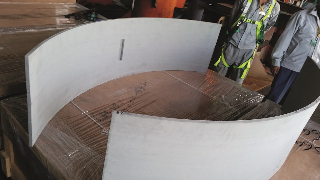
Sulzer offered a third, more time-efficient, economical and long-lasting option: weld overlay. By using this in situ process, it is possible to cover large column surfaces with corrosion-resistant alloys. The company is highly experienced in this technique and has developed an advanced, fully automated weld overlay equipment to support its operations.

This machine consists of a carriage travelling along a laser-levelled track system fixed to the column shell wall. On the carriage, a robotic index arm moves the welding torch and the oscillator to create weld beads. All the relevant process parameters, such as carriage speed or bead thickness, are controlled by a programmable logic controller (PLC), with which human operators can communicate by means of human-machine interfaces (HMIs). One single PLC can monitor multiple welding machines following the same instructions.

The automated process can quickly perform welding with high accuracy. As a result, customers can benefit from a high-quality and consistent process as well as short downtime. In this case, Sulzer could complete the overlay of the 110m2 VDU corroded surface in the time allocated to 65m2.

To reduce the likelihood of future corrosion, the VDU column shell was overlaid with layers of austenitic stainless steel type 316 alloy, which is widely used in welding processes to avoid carbide precipitation. In addition, the presence of molybdenum and nickel makes the alloy suitable for applications in harsh conditions.

Comprehensive corrosion protection

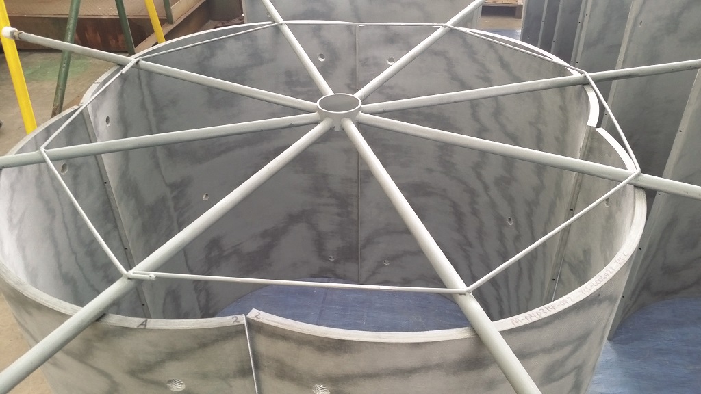
In addition to repairing the VDU column shell, Sulzer also performed weld overlay on the corroded surfaces of the other two towers, namely the ADU and the third fractionator. Also, column internals, such as trays and packings, were replaced to further improve the performance of the entire oil distillation system.

The weld overlay process was performed in two weeks, while the entire revamp was concluded in 25 days, without any delays despite the discovery of larger corroded areas within the VDU, increasing the required weld overlay to almost double that of the originally estimated area.

Since the revamp, the refinery has operated smoothly at full capacity and the solution from Sulzer could also support the shift towards different crudes without affecting the columns’ corrosion resistance. The customer was so pleased with the work that it offered to provide a positive reference to any potential customers of Sulzer.

Andrew Petticrew at Sulzer Tower Field Services, comments: “The ability of our experts to resolve unexpected issues, coupled with our automated weld overlay capabilities, were crucial to ensure the timely repair of the corroded column shells. In addition, the customer could benefit from a one-stop-shop for the revamp project, as we took care of dismantling the existing column internals, as well as the manufacture and installation of new ones.” 


The impact of COVID-19 on the oil industry

$
0
0

After a rocky few years, the oil industry is forecasted to see a decline in oil demand growth for the first time since 2009. The IEA is expecting the first quarter of 2020 to see the demand decrease by 2.5 million barrels per day year-on-year.

March Oil Market Report summary

The IEA Oil Market Report provides authoritative data, forecasting and analysis of the global oil market. March sees their latest report which, of course, discusses the impact COVID-19 has had on the market.

As coronavirus spreads across the globe, the IEA is estimating a fall in demand by 90 kb/d year-on-year. In 1Q20 alone, global demand has decreased by 2.5 mb/d. The assumption is that we will see demand return in 2H20 to almost normal.

In addition to a fall in global oil demand, the IEA reported a decrease in global oil supply in February of 580 kb/d and estimates that 2020 global refining throughput will fall below 2017 levels for a second consecutive year. The decrease in throughput is directly associated with coronavirus, due to the decreased demand in transport fuel.

January saw OECD industry stocks increase by 27.8 mb, reaching 2930 mb. As promising as this looks, it was actually due to product inventory building offsetting counter-seasonal draws of crude stocks.

Coronavirus and the oil market

On March 23rd, the World Health Organisation confirmed that cases of coronavirus have surpassed 300,000. The impact of COVID-19 on the oil industry is predicted to result in the first full year decline in over ten years.

China accounted for over 80% of oil demand growth globally which has played a role in this decrease. While data collection has not yet been completed, the first quarter of 2020 has seen a marked decline in commercial and industrial activity points and transport. This has resulted in global oil demand dropping by 2.5 mb/d comparative to the same period last year.

The IEA Oil Market Report states that the oil market outlook will be dependent on government efforts to contain the outbreak, the success of any actions taken and the ‘lingering impact’ the crisis has on economic activity. In light of this, the IEA has had to propose base case alternatives, including both a pessimistic and optimistic outlook depending on the continued impact of coronavirus, which can be found in the report.

The IEA’s pessimistic low case

This case expects countries that have already been impacted by the virus will see a slow recovery as the pandemic continues to spread. It takes into consideration that efforts to control the propagation of the virus will take longer, while oil demand in China will ease more slowly throughout March.

The third quarter of 2020 will see European oil demand continuing to be subdued, with US demand growing at a reduced pace. The IEA predicts that in 2020, oil demand could potentially decline by 730,000 barrels per day in this case.

The IEA’s optimistic high case

The optimising high case is based on the assumption that China can bring the outbreak swiftly under control and that more severe contagion is limited to a few countries, with Europe and North America seeing no serious impact. In this outlook, government containment does not require strong measures and transport use ‘remains closer to normal’. Predictions by the IEA, in this case, see 2020 oil demand growing by 480,000 barrels each day.

The World Health Organisation has reported that the coronavirus pandemic is accelerating. This, along with government action, means the full impact of coronavirus on the oil industry is yet to be seen.

Oil tanker successfully tests marine biofuel

$
0
0

The 49,646 deadweight tonne (dwt) MR tanker received the first delivery of Bio Fuel Oil during its recent call at the Port of Rotterdam. The fuel, which GoodFuels launched in 2018, reduces greenhouse gas emissions by 83% and substantially reduces SOx emissions. 

The trial was completed on the Stena Immortal as she ran on a typical commercial operation. During the trial, BFO was tested in tanks, storage and as it was burned in the engines, the fuel proved to be a technically compliant alternative to the fossil default for oceangoing tanker vessels.

The success of this trial underlines sustainable marine biofuel's position within the marine mix, and helps owners and operators to future-proof against current and impending regulations. As the trial was conducted with 100% biofuel, it also shows that low-carbon shipping doesn't have to be decades away but viable also on the shorter term if industry leaders work together to push the development.

Because it substantially reduces CO2 and SOx emissions, GoodFuels' Bio Fuel Oil ensures compliance with the International Maritime Organisation's (IMO) 2020 Sulphur Cap, Greenhouse Gas (GHG) reduction requirements and upcoming regulations to reduce carbon intensity from shipping.

"We like to show the industry that we can start reducing the carbon footprint of shipping here and now while maintaining highest quality technical and commercial operations. The Stena Immortal performed very well running on the biofuel while continuing to deliver according to our customers' needs without any disruption", said Erik Hånell, President and CEO Stena Bulk.

"The industry needs pioneers willing to collaborate, share knowledge and push the development towards more sustainable shipping. We're happy to collaborate with GoodFuels in this test to take on that mission and encourage others to join us. We are of course open and have a willingness to drive and take part of this development together with stakeholders in this industry,” Hånell continued.

"We are delighted this test with Stena Bulk was a success and want to thank them for joining us in our mission to develop a carbon-busting solution that is scalable, truly sustainable, technically compliant and, crucially, affordable", Dirk Kronemeijer, CEO, GoodFuels Marine, commented on the successful trial.

"For the past five years, we have focused on realising the widescale use of sustainable marine biofuel, which has enabled us to continue to develop biofuels as a true solution to the market's problems. This marks yet another a crucial move towards offering the shipping industry a credible near-zero carbon alternative to HFO and VLSFO."  

Stena Bulk and GoodFuels Marine will continue working together to gain more experience and scale the usage of Bio Fuel Oil as an alternative to conventional fossil-based fuel. 

The fuel is sustainably sourced and completely derived from forest residues and waste oil products. It is verified by an independent sustainability board of leading academics and NGOs. 


New cleaning solution from Holdtight proves popular in oil and gas sector

$
0
0

It’s no secret that coatings last longer and perform better on a clean surface. Most cleaning methods, however, cause problems of their own. Dry blasting shatters the rust and coating on the surface and embeds abrasive contaminants to become stuck into the roughened surface. Wet abrasive blasting with untreated water causes flash rust. Other salt removers only remove a few salts, while replacing them with other salts and leaving behind an acidic, conductive residue. A new solution from a US-based company offers impressive cleaning without contaminants, flash rust, residue or film. It is naturally proving popular in the oil & gas sector – a market where durable, corrosion-resistant coatings are an absolute necessity.

HoldTight completely removes all salts and therefore all conductivity. It also removes abrasives and debris from the surface’s profile, providing a better surface area to bond with coating. Since it leaves a clean, rust-free surface for up to 72 hours, large areas of structures can be blasted and cleaned completely before coating application, instead of having to be coated immediately after blasting every day.

The product can be worked into any blasting process to achieve a totally clean surface, with zero flash-rust and zero residue left behind. It is a clear, simple additive with visible results, eliminating both natural and artificial contaminants. Throughout the oil & gas sector – from upstream to downstream – the solution is safe to use and compatible with a wide variety of surfaces, including steel, concrete, fibreglass, aluminium and composites.

Blasting water treated with HoldTight onto a surface prior to coating removes all naturally occurring contaminants (salts, acids, conductives). The solution also removes byproducts of the blasting process (shattered abrasives, dried paint) lodged within the pores of the surface, allowing for the most adhesive bond possible between the surface and the coating.

The cleanest surfaces are achieved when the product is used in both the blast and wash-down cycles at a 50-100 (water to HoldTight 102) ratio. The product extends the life and value of oil & gas assets for just pennies per application.

Operators can also save time and money with HT 365, a new thin-film coating that can be applied to blasted surfaces, preserving the blast and preventing flash rust and corrosion for up to one year. It can be applied to untreated surfaces or those that have been treated with HoldTight 102.

By preserving the blast for up to one year, HT 365 allows personnel to work with maximum efficiency, giving operators peace of mind that their surface is properly prepped for a quality coating – even if the project cannot be completed right away.

This new product is easily applied by brush, spray or dipping and easily removed by high-pressure washing with HoldTight 102-treated water.

Ken Rossy is with HoldTight. www.holdtight.com


Analysing Valves And Pumps With Torque Transducers

$
0
0

To analyse the long term performance and reliability of hard working valves and pumps, serial innovators Manchester-based Bifold Group has adopted radio frequency based torque transducers from Sensor Technology Ltd for two of its specialist test rigs.

By using the power of computer aided design many of Bifold’s products are built to custom designs, yet they are produced to very short lead times thanks to the efficiency of internet communications. To maintain this standard, sample products and components are comprehensively tested so that their reliability and capabilities are never in doubt.
   
So when Bifold wanted to assess the effects of wear on its long-life valves they set about designing a special test rig. Engineer Andrew Laverick recalls: “We wanted to measure the power required to operate the valve to see how it changed over time and with long term use. It was clear that the best way to do this was to measure the torque input over an extended period.”

“We were open to any design concept for the test rig, but soon found ourselves gravitating towards a TorqSense solution because the Sensor Technology engineers were so helpful and really knowledgeable about test rigs.”

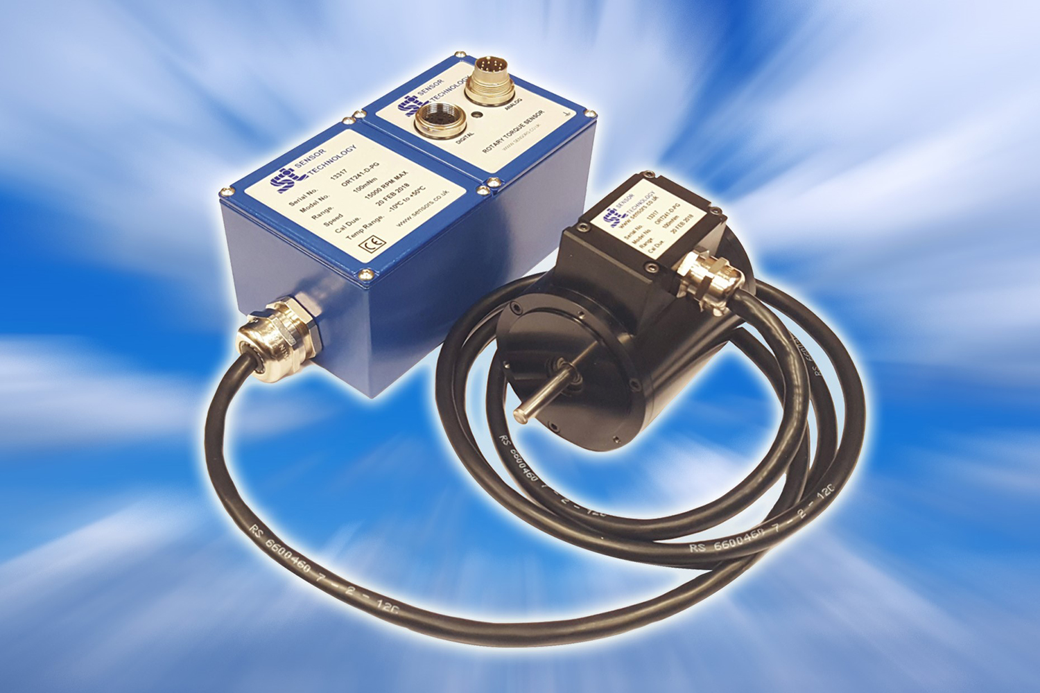
TorqSense transducers lend themselves to test rig uses because they are non-contact measuring devices. Attached to the surface of the transducer shaft are two Surface Acoustic Wave (SAW) devices, when torque is applied to the shaft the SAWs react to the applied strain and change their output. The SAW devices are interrogated wirlessly using an RF couple, which passes the SAW data to and from the electronics inside the body of the transducer.

Sensor Technology’s Mark Ingham explains: “All you have to do is set up a TorqSense transducer in the test rig and fire it up. The SAW frequencies reflected back are distorted in proportion to the twist in the test piece, which in turn is proportional to the level of torque. We have some clever electronics to analyse the returning wave and feed out torque values to a computer screen.

“TorqSense has been used on many test rigs over the years and I was delighted to hear the Bifold engineers say how easy it is to use and how robust the software is.”

Laverick again: “As a test engineer you are almost resigned to long set up procedures and software that falls over at the drop of a hat. But Sensor Technology has designed these problems out of their TorqSense equipment, with the result that we were able to complete our long term test procedures with the minimum amount of fuss and heartache and well within the allotted time schedule.”

In fact Bifold has since bought a second TorqSense which is being fitted to a new test rig used to assess the performance of mission critical chemical injection pumps, as used at oil and gas wellheads and on process pipelines.

“This project is proceeding well,” says Laverick, “and is allowing us to further develop our abilities to quickly provide bespoke equipment for ultra demanding applications, safe in the knowledge that it will perform faultlessly over a long working life.”


Mega-project technology

$
0
0

Peter Johnson explains why a big LNG project calls for an engineered solution

Globally, this particular LNG project is a very significant, large and technically complex, energy development. In essence, the project is ingenuity at its best. Innovative technologies have been used where possible to deliver this project and ensure that once in operation, it continues to run with little to no downtime.

Located about 220km offshore Western Australia, the field represents the largest discovery of hydrocarbon liquids in Australia in 40 years. This LNG project is currently in construction and is ranked among the most significant oil and gas projects in the world. It is effectively three mega-projects rolled into one, involving some of the largest offshore facilities in the industry, a state-of-the-art onshore processing facility and an 890km pipeline uniting them for an operational life of at least 40 years.

In operation, it is expected to produce at capacity up to approximately 8.9 million tonnes of LNG per annum and 1.6 million tonnes of LPG per annum, in addition to about 100,000 barrels of condensate per day at peak. A Final Investment Decision was reached in 2012 and first production is scheduled to commence towards the end of 2018/beginning of 2019.

Fabrication

The construction work for the offshore facilities was carried out at a shipyard with the responsible classification society. Offshore facilities consist of a CPF (Central Processing Facility) and an FPSO (Floating Production Storage Offloading). On the CPF there are several risers and riser guide tubes that will be placed around the facility. Due to the size of the columns, they need housings to ensure alignment. There have been concerns that movement of the columns against the housings will cause erosion-corrosion and impact. As the CPF has a design life of 40 years, it was decided to protect the columns and housings with composite bearings.

Composite bearings are generally installed around propulsion areas on ships. There are several ways to install bearings, however once they reach a certain size, the best option is bonding. Due to the size of the bearing required, in this case bonding was the only option to choose.

Belzona has vast experience bonding composite bearings, especially around rudder pintle areas on ships. After a trial ship application in 1979, the material was accepted as a permanent installation and used from new on all Germanisher Lloyd classed vessels. One of the first and perhaps most notable bearing bonding applications in service today was performed on a flagship liner, Queen Elizabeth 2. Bearing bonding is carried out by injecting the Belzona material between the bearing and the housing. The Belzona shim takes up any ovality or housing wear, thus creating a durable barrier with 100% surface contact, electrically isolating the bearing.

There are other adhesive products available on the market, however due to the 40-year design life, Belzona was chosen due to impressive testing, case histories. The company holds a certification for the products that are used in this process.

Bearings split into sections

The bearings were supplied in various sizes to match the columns and housings; some of the bearings reached 2.5m in diameter and 3m in length. As the sizes were so large, the bearings were split into sections. This meant that once the bearings were in place, the seams between each section would have to be dammed to stop the injected adhesive from leaking.

Belzona 1321 (Ceramic S-Metal) was used as the adhesive to inject between the housings/columns and the bearings. As Belzona 1321 does not cure based on a high exotherm, unlike chocking compounds, the gap could be reduced between bearing and substrate. This reduction of product quantity and application time ultimately saves on costs to all.
 
Due to the scale of this application, specialised techniques were created by Belzona Asia Pacific staff and the application team were trained up on life-sized equipment. One of the new techniques adopted was the use of a nylon jacking bolt which doubled up as an injection port for the Belzona 1321. This saved on the amount of holes that needed to be drilled into the composite bearing.

Belzona inspectors were present during the whole application in Geoje and ensured that the high standards were kept through use of QA/QC documentation.

This LNG project is now nearing completion, scheduled to go in production towards the end of 2018/ beginning of 2019. This project has truly been a testament to modern engineering and it will not be long before it commences its 40-year life, bringing much needed resources and infrastructure to the local and global community.

Typhoon Valve System Wins ONS2018 Innovation Award

$
0
0

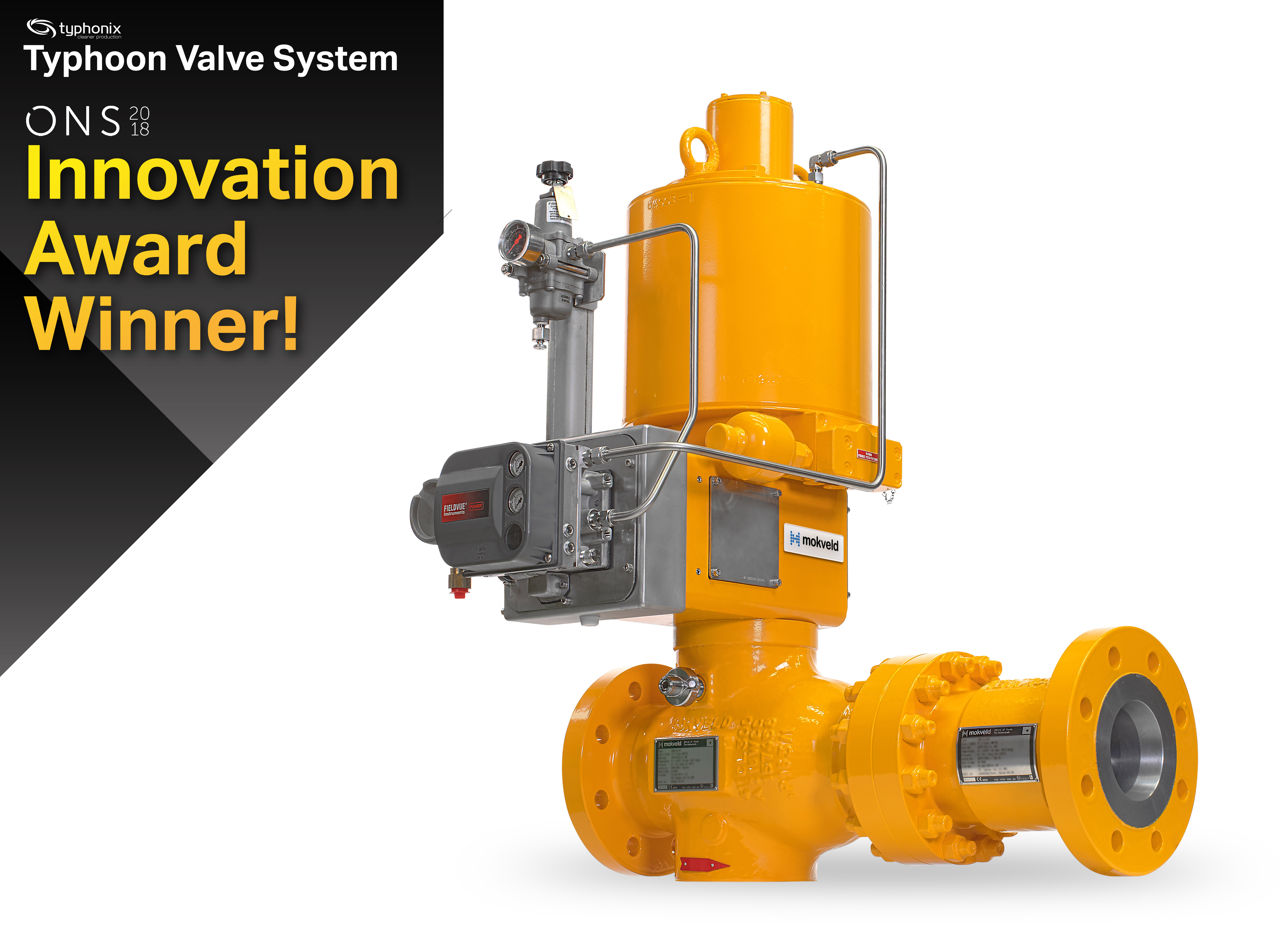
Low shear technology developed by Typhonix and used in the Typhoon Valve Systems is the Innovation Award Winner of this year at ONS2018 in Stavanger, Norway. Winning the Innovation Award is a recognition for Typhoon Valve System and confirms the prowess of Typhonix and Mokveld in low shear valve technology. Where Typhonix in Norway is developing the low shear technology and Mokveld Valves BV in The Netherlands is manufacturing the Typhoon Valve Systems.

By reducing shear forces in control valves and choke valves, Typhoon Valve System is a cost effective solution for cleaner production. It is the most cost-efficient solution to debottleneck separation and produced water treatment systems as it does not require any additional equipment, simply replace the existing valve.

In every process plant you will find sources of unwanted shear forces creating emulsification of oil and water. The main principle behind low shear processing is prevention of separation problems caused by droplet shearing of the production fluids in conventional valves. Replacing these existing valves to low shear versions gives significantly improved separation and less oil residues in the produced water.

In contrast to conventional choke and control valves, Typhoon Valve uses patented trim technology to involve a larger fluid volume that is actively dissipating energy. By using low shear valves and pumps it is also estimated that greenfield separation plants can be built 30-50% lighter and smaller, which will have large cost saving potential on both OPEX and CAPEX for the oil companies.

Typhoon Valve System enables users to reach higher well production rates, to extend late-life field production, to reduce the footprint of the process plant and of course to produce cleaner oil or produced water.

Managing your warehouse without spreadsheets

$
0
0

Knowing your inventory is an absolute necessity and how well you manage it directly affects your bottom line. Arguably, the materials that go into building any facility are the most important part of the whole project. This holds true for all parts of the oil and gas value chain - downstream, midstream, and upstream. There are a lot of moving parts to keep track of and your inventory is mobile, so why shouldn’t you be?

The 2018 MHI report states that while the current adoption rate of mobile technologies in supply chains is at 23 percent, it is expected to surge to 73 percent over the next five years. Mobile inventory management is growing, and to stay ahead of the competition, companies can’t get left behind by waiting to adopt mobile technologies.

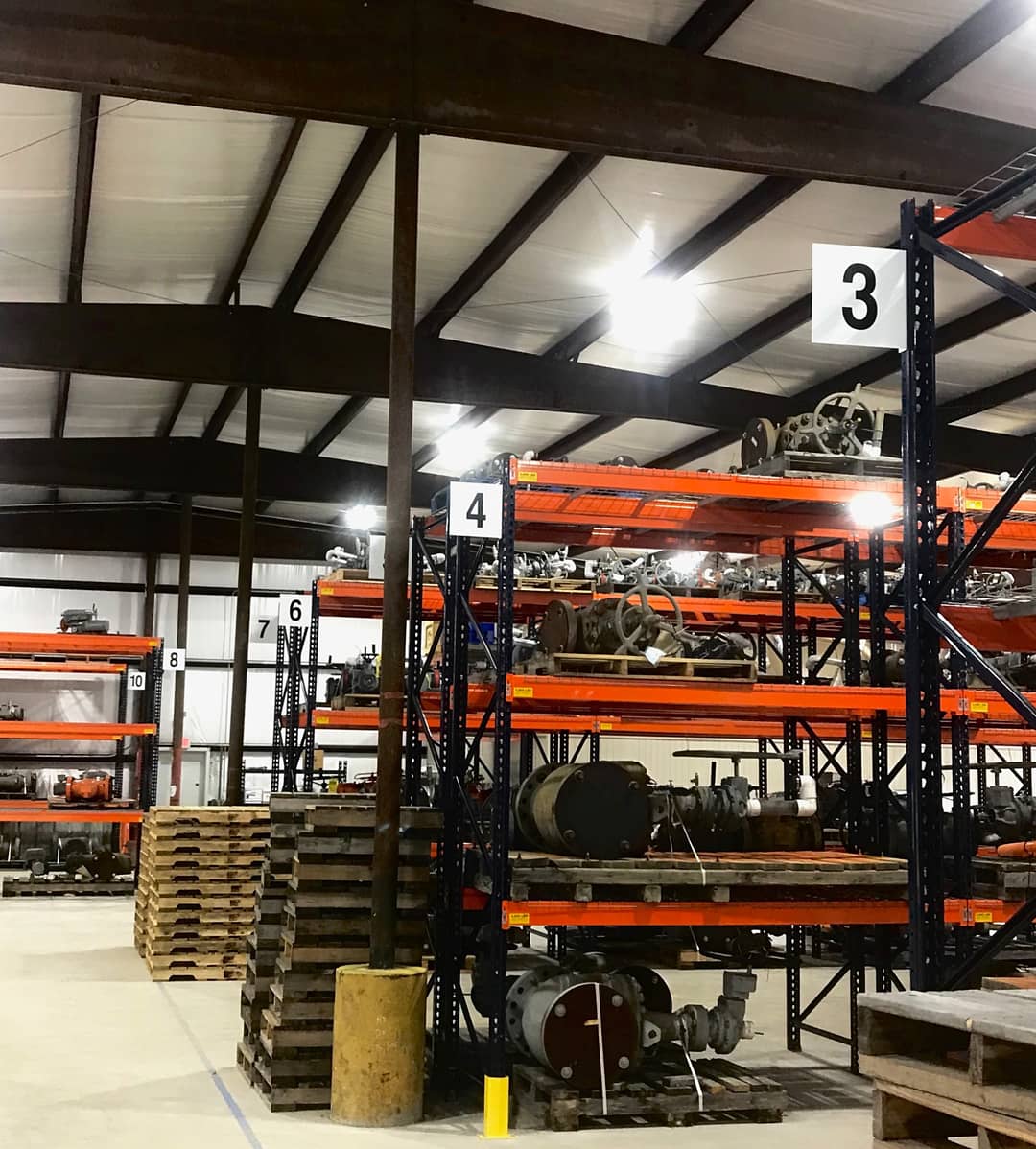
Efficient inventory control means that inventory is not tied up when it is uncalled for. It means having 100% inventory visibility, and avoiding spending money on new materials without prior knowledge of what exactly is in your inventory. Inventory issues can arise if you don’t have current and real-time stock reports of everything that is currently in the yard. Mobile inventory applications create more inventory visibility that leads to reduction in redundant procurement, minimizes leakage and maximizes utilization.

Lack of knowledge of stock positions can hurt your bottom line. Having a warehouse management solution that can tell you what you have in stock at any time, and in real-time, can make a big difference in supply chain optimization. Once your business has a more efficient process in place, there is a positive effect on customer service, which is much needed at a time when customer service expectations are already at an all time high. Think of the innovative retail giant Amazon. Amazon will do everything in their power to remain customer focused, and they have the supply chain technology to back it up. Though, your warehouse is likely not ready to start testing with drones or augmented reality, there are lessons that can be learned from Amazon’s drive for achieving optimum supply chain management and the importance of customer satisfaction.

Concerns about lack of internet connectivity? No problem. Offline mode in mobile is available for operations in remote areas. Cloud based inventory management delivers a seamless solution for mobile and desktop. Using mobile devices improves the way you track what materials come in, what materials are shipped out, and what materials remain in the storage yard. All of this captured data is received through pre-configuration and barcode scanners on a mobile phone. This system tracks materials and empowers employees with linked access to detailed inventory records whenever they need it.

There are a handful of compliance and regulatory requirements that are of concern when you’re managing pipeline inventory. Regulatory requirements such as:

  • Individual product specifications
  • Material Test Records
  • Reference documents
  • Health, Safety, Environment, and Quality (HSEQ) requirements
  • Technical requirements
  • Transportation & Handling Requirements

Having your materials and inventory in check (on a mobile and desktop environment) leaves one less step to stress over. Accessible documentation is the key to compliance, and having a digital inventory management solution makes all of that paperless! Information about specs becomes easier to retrieve with warehouse inventory management software. Collaborate across your organization, and share data with ease. Not only can you enhance mobile capabilities but you can do even more by integrating with ERP systems.

The implementation of innovative technologies in supply chain increases transparency and encourages quick information sharing across the enterprise. If you would like a demo of Petro IT’s Stack61 to help with your material and inventory management (Stack61 is an Intelligent Warehouse Inventory Management Solution by Petro IT) please click here.


Novel solution in the fight against pipeline corrosion

$
0
0

Ed Hall reveals how a novel solution is helping in the fight against corrosion

Corrosion is one of the biggest unforseen costs that oil & gas operators face and it is cited as one of the major issues for pipeline failure in oil & gas and chemical process plants. The Worldwide Corrosion Authority, NACE, estimates the cost of corrosion is more than US$2.5 trillion, which is roughly 3.4% of the world’s gross domestic product (GDP).

Predominantly influenced by the surrounding environment, corrosion can form quickly and un-noticed around the connection of a pipe, metal contact points, within the crevices of bolt heads and nuts, in steel to concrete interfaces or between a flange face and valve fitting.

Without routine maintenance corrosion can lead to serious safety risks and environmental hazards, such as leaks, which incur significant penalties. Within the pipeline, failure to identify and resolve corrosion will ultimately lead to a failure to operate.

The costs to shutdown a pipeline due to corrosion would be considerable in both material, labour and downtime. Simply cutting away corroded bolts is a task that can add two to three days to maintenance. In these situations a preventative approach is best adopted ideally before signs of degradation occur, but at least when corrosion is in early stages and equipment is still fully operable.

Pipe support corrosion protection and integrity maintenance solutions - Some examples from the field

It is well documented that pipe supports are the second biggest issue of corrosion on external piping after corrosion under insulation (CUI) in a wide range of industrial plants and offshore topside process piping. The primary location for corrosion is at the 6 o’clock position where it is difficult to identify without close visual inspection or through the use of costly inspection equipment. It is not always safe and will often require detailed analysis prior to lifting for inspection purposes due to the design of some clamps and supports that could result in a risk of damage and or product release, resulting in safety issues.

50-60% of all pipe corrosion leaks are caused by contact point corrosion as found with corrosion under pipe supports (CUPS).

What is a pipe support?

A pipe support is usually made out of steel, providing a framework of a certain distance from the ground to support and distribute the weight of suspended pipes. They typically comprise of structural steel such as I-beam, angle and channel section. These pipes are normally secured to the member using u-bolts. Also found in such facilities are either half or full saddle clamps, and welded supports/guides which allow movement of the pipe within the support, but they also invite corrosion. These pipes can be carrying a variety of substances; water, gas, oil, chemicals, petrol, saltwater – anything that travels through a pipe.

The environment is typically aggressive from a corrosion standpoint, with exposure to water, chemicals, salt, humidity and abrasion often present. Due to the shape and contours of the pipe support, these corrosion accelerants are easily trapped between the pipe and the support, allowing corrosion to develop. Since they are so difficult to visually inspect it is often too late to identify when the crevice corrosion has begun.
 
Many common solutions used to eliminate this problem can actually aggravate the situation as they still allow for the accelerants to sit against the live pipework. Liners and rubber pads, fibreglass pads to name a few have all failed, as they do not eliminate the water and corrosion continues.

Many solutions that are available in the marketplace require a shutdown to install the solution and even then only when they are replacing pipework, such as the use of half round plastic rods which minimise the contact point of metal to metal. In a best-case scenario these solutions are fitted at the outset of pipe installation.  

Even during a shutdown, if the operator is not intending to replace the pipework, they are reluctant to remove u-bolts/hangers/clamps, and lift the pipe to install these, as they do not want to risk the possibility of damage to the pipework.

The ultimate solution

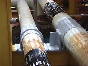
Oxifree has developed an innovative coating encapsulation, TM198. This thermoplastic coating is organic and provides a protection solution that halts, mitigates and eliminates (further) corrosion to pipe supports and other complex structure interfaces.

The coating is melted down from a solid resin (in the supply unit) and applied using a heated hose and gun to fit the contours of any complex component. A key feature of the TM198 encapsulation system is the non-adherence to the substrate, along with self-lubricating properties, which allows any pipework that needs to move within the clamp to also move within the TM198. This makes it suitable for a wide range of piping where pipes expand and contract or subject to vibration, even on FPSOs. Indeed, the coating is now being used globally to halt the issue of CUPS for oil and gas majors.

Whereas other solutions require a shutdown and take time to install, the Oxifree coating can be applied to live pipework and provides protection immediately, as it cools on impact, saving considerable downtime cost, and no disruption to production. This makes it complementary to (applied alongside and/or over) other protective solutions.  

Once the pipe, saddle and clamp are encapsulated, the surface within is protected from moisture and oxygen protecting it from further degradation.

This novel solution is only applied once and will provide many years of protection in the harshest of environments. Should inspection be required this can be done through the coating with the use of NDT/ANDT inspection techniques (such as UT) or a small area cut away from the coating for visual inspection and can simply be refilled/resealed.

The oil & gas industry is still facing the challenge to reduce unnecessary expenditure and make critical savings to maintenance, while increasing safety and reducing ecological impact. Extending asset lifespan without operational shutdown is the fundamental way forward. Creating a culture of prevention with new technologies will be the ultimate solution.

Kazakhstan’s first world-scale GSU project

$
0
0

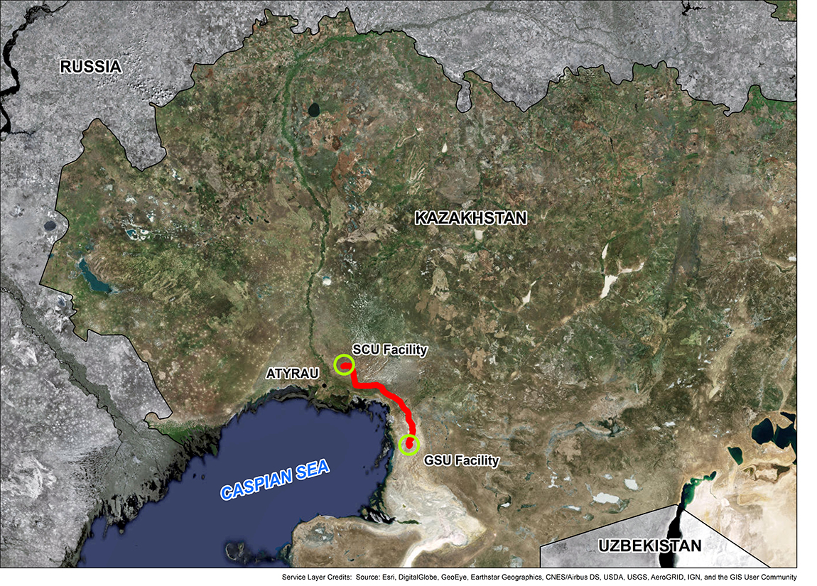
KLPE, an affiliate of United Chemical Company (UCC), initiated Kazakhstan’s first world-scale GSU project supplying feedstock to the polyethylene plant in Atyrau Region with a total capacity of 1,250 ktpa, which is executed in the framework on a joint development agreement between UCC and Borealis.

ILF Consulting Engineers (ILF) has been awarded with project management consultancy (PMC) services, including the supervision of the detailed feasibility study (DFS), to support KLPE, delivering this strategically important project.

“These strategic UCC initiatives pave the way in establishing the Republic of Kazakhstan as a global player on the polyolefin market. By using advanced technologies, engaging leading contractors and suppliers, as well as targeting for high levels of safety, reliability and operability, we aim to ensure the maximum return of capital investments,” says Maksim Sonin, UCC project portfolio managing director, member of the board.

“ILF is proud to support KLPE in this professionally led and fast progressing project. With the team’s ability of integrating ILF’s Western project management and Kazakh engineering requirements with local state-owned project execution processes, as well as permitting expertise, I am highly confident that the DFS phase will create the maximum value for UCC and its partner supporting their strategy of sustaining Kazakhstan’s development in the polyolefin market exploitation,” adds ILF project manager and area manager Upstream, Helge Hoeft.

The heart of the project is the NGL recovery facility, located close to the Tengiz oil field, with a maximum feed gas capacity of over 7 billion Sm3/a recovering ethane and heavier components as feedstock for the polyethylene project. In addition, a feed gas pipeline from TCO’s facilities, an approximately 180km long C2+ export pipeline to the polyethylene plant and a redelivery gas pipeline to GEEP pipeline, are within the project scope.

How To Reduce Motor Downtime On Offshore Oil Platforms

$
0
0

Constant monitoring of critical motors and generators on offshore oil platforms while offline prevents failures on start-up, reduces production interruptions, saves on rewinding repairs and increases personnel safety

For decades, offshore oil and gas personnel have performed insulation resistance tests with handheld megohmmeters to prevent motor and generator failures that lead to costly unplanned shutdowns, production interruptions and rewinding repairs. However, these tests only provide a snapshot of motor or generator health. In a matter of only a few days, windings and cables that are exposed to salt air, moisture, chemicals, contaminants or vibration can become compromised and fail at start-up.

The Challenges Of Megohmmeters

Portable megohmmeters also require electrical technicians to manually disconnect the equipment cables and connect the test leads on potentially energised or damaged equipment to perform the manual testing. These tests expose technicians to potential arc flashes when they access the cabinet. In the USA, non-fatal arc flash incidents occur approximately five to 10 times per day, with fatalities at the rate of approximately one per day.

With so much at risk, offshore platform operators are recognising the value of continuous megohm testing and monitoring of insulation resistance that initiates the moment the motor or generator is off and continues until it is re-started again.
 
Armed with this information, maintenance personnel can take corrective actions ahead of time to avoid a failure that would interrupt production. By doing so, they can save oil and gas producers hundreds of thousands of dollars in lost production and repair fees for expensive rewinding as well. Furthermore, permanently installed automatic testing devices allow for ‘hands-off’ monitoring without having to access cabinets – keeping technicians out of harm’s way.

How To Protect Motors On Offshore Platforms

Offshore platforms rely heavily on their main generators and a variety of motors, though the number and type vary depending on the size of the platform and rate of production. On a deepwater or ultra-deepwater platform, several hundred motors may be installed, with five-10 categorised as critical or significant (high-cost motors that are not easily replaced). On exceptionally large platforms, up to 30 critical motors might be involved.
 
These motors, which can range from 460V up to 13,200V, are found in crude oil export pumps, circulating water (saltwater, utility, fresh) pumps, fire pumps, cement pumps, gas compressors and fans. Medium-voltage generators in the main power plant, as well as low-voltage standby generators that back up the main generators and power lifesaving equipment are also critical to the operation of the platforms.

Unfortunately, this equipment is subjected to ice, moisture, changing temperatures and dense salt-fog. The salt-fog is one of the worst problems because the salt, combined with the moisture, can cause severe damage to the electrical insulation inside the critical motors and generators.

“The offshore environment is probably one of the harshest environments for electric motors and generators,” says Donna Lee Hodgson, senior electrical engineer for Shell International Exploration and Production. Hodgson currently designs deepwater facilities for projects in the Gulf of Mexico. “I have seen motors come into the shop that have salt encrusted on the interior of the stator windings,” says Hodgson.

Sand is also prevalent on deepwater platforms given the constant sandblasting and re-coating of carbon steel structures. “Basically, the sand that you are blasting at the carbon steel structures around the equipment tends to get into the motors and generators too,” explains Hodgson. The sand breaks down the insulation coatings on the windings, which leads to premature failures. The environment is so corrosive that Hodgson typically specifies enclosed or weather-protected motors.

Preventative Maintenance Programmes

In addition, most offshore oil operations engage in a time-based preventative maintenance (PM) programmes. As part of the programme, insulation resistance tests are typically scheduled on a semi-annual or annual basis. Typically, insulation resistance tests are also conducted at the start of annual overhauls or planned outages, to identify any motors that need repairs.  

According to Hodgson, critical motors on the deepwater platforms are tested to determine the equipment’s Polarisation Index (PI). The PI is used to determine the fitness of a motor or generator and is derived by calculating the insulation resistance of the windings using a portable megohmmeter.

The test begins with a reading of insulation resistance recorded at one minute, then a second test reading is taken for 10 minutes. The ratio of the two measurements provides the PI, which should be above 2.0.

Still, despite these types of tests, motors and generators can become compromised within only a few days in the corrosive, dirty environment and fail at start-up. When this occurs, costs quickly mount for “rewind” repairs or replacing the motor or generator while production comes to a halt. “Failures can be really expensive. Rewinds can cost tens of thousands of dollars, up to a couple hundred thousand depending on the type of motor or generator,” says Hodgson.
 
“And it is not just the cost of the repair,” she adds. “It is also the cost of the labour to get the motor or generator prepped and ready for shipment, the cost for the boat to bring it to and from the platform, and road transport. Those costs can also run in the tens of thousands of dollars.”

To avoid these costs, electrical engineers are turning to a continuous monitoring device, the Meg-Alert. Hodgson says she first heard about the automatic insulation resistance testing device through some of her colleagues.

What Is A Meg-Alert?

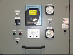
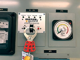
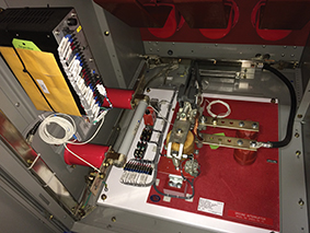
The Meg-Alert unit is permanently installed inside the high-voltage compartment of the MCC or switchgear and directly connects to the motor or generator windings. The unit senses when the motor or generator is offline and then performs a continuous dielectric test on the winding insulation until the equipment is re-started. By testing continuously, it reduces the need for manual PI testing since the insulation resistance readings are averaged over a longer period of time to determine the true ‘leakage current’ level of the insulation.

The unit functions by applying a non-destructive, current limited, DC test voltage to the phase windings and then safely measures any leakage current through the insulation back to ground.  The system uses DC voltage levels of 500, 1,000, 2,500 or 5,000V that meet the IEEE, ABS, ANSI/NETA and ASTM International standards for proper insulation resistance testing voltage based on the operating voltage of the equipment. The test does not cause any deterioration of the insulation and includes current limiting technology that protects personnel.

The Meg-Alert device can also be installed to disable the start circuit to prevent the motor or generator from being operated if the insulation resistance level is unsafe for operation. It is for this purpose that Hodgson installs the device on the generators on the deepwater platforms. “The Meg-Alert is wired to the start circuit so when you hit the ‘start button’ you get an automatic insulation resistance test and if it doesn’t stay above a certain setpoint, it will not start the generator,” explains Hodgson. “What that does is take human error out of the equation.  No one has to remember to use a megohmmeter before starting up the generator – the test is automatic and the equipment will not start if it’s not safe to use,” says Hodgson.

The Benefits Of Hands-Off Monitoring

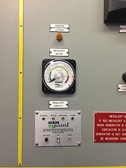
The continuous monitoring system also allows for a hands-off approach that does not require service technicians to access control cabinets to perform a manual insulation resistance test. Instead, an analogue meter outside on the control cabinet door shows the insulation resistance megohm readings in real time. The meter also indicates good, fair and poor insulation levels through a simple “green, yellow, red” colour scheme. When predetermined insulation resistance set point levels are reached, indicator lights will turn on to signal an alarm condition and automatic notifications can be sent out to the monitoring network.

“With the Meg-Alert, personnel do not have to open junction boxes and connect a megohmmeter to the motor or generator. They can just look at the meter and alarm lights on the panel,” says Hodgson.

Continuous monitoring also indicates if the heaters used to maintain thermal temperatures and prevent condensation from forming on the stator coils and cables are working properly. If these heaters fail to operate properly or the circuit breaker is tripped, maintenance personnel may not be aware of it until the motor or generator fails on start-up. Although these heaters are checked regularly, this can leave critical motors and generators unprotected for weeks or even months.

How To Prevent Arc Flashes

According to Hodgson, safety is another major driver behind the decision to install the Meg-Alert devices. Arc flashes are an undesired electric discharge that travels through the air between conductors or from a conductor to a ground. The flash is immediate and can product temperatures four times that of the surface of the sun. The intense heat also causes a sudden expansion of air, which results in a blast wave that can throw workers across rooms and knock them off ladders. Arc flash injuries include third degree burns, blindness, hearing loss, nerve damage, and cardiac arrest and even death. Among the potential causes of an arc flash listed by NFPA 70E includes “improper use of test equipment.”

Although de-energising equipment before testing and wearing appropriate personal protective equipment (PPE) is recommended, the best solution is to eliminate the need to access the control cabinets at all to perform insulation resistance tests. “Two hazards we would be concerned about on a platform are electrocution and arc flash,” says Hodgson. “Given that generators on platforms are located within feet of the load, this is even more of a concern because of the high short circuit currents.”  


How Safe Are Flanges?

$
0
0

Welding is still the most widely recognised method for joining pipe systems together. However, there’s an additional connection technology that is worth considering: the High Performance Flange (HPF) system.  Ramiz Selimbasic details this time-saving and cost saving alternative to welding.

What Is The High Performance Flange (HPF) System?

The High Performance Flange (HPF) system is coordinated to common pipe sizes from 25 to 150mm diameter and wall thicknesses up to 20mm. It is designed for flange sizes ¾ to 5in hole patterns according to ISO 6162-1/2 (Code 61/62), ISO 6164. High-performance flanges are manufactured as finished machined and type approved according to International Association of Classification Societies (IACS). This therefore results in consistently high precision and quality during processing, so that these components no longer have to be reworked at the installation site.

The best solutions for complex design problems can often be found in nature. The flaring of a tube is similar to the shape of a branch where it joins the trunk of a tree. The tube is flared by hydraulic axial pressure giving it a parabolic shaping, increasing from 10° up to 37°. The initial gentle incline of the shaping guarantees additional safety against strong system vibrations.

The most essential part of the HPF connection is the locking flange design, which supports the pipe from the outside and provides additional protection against it tearing out of the connection. An insert is placed into this specially formed pipe. This insert seals on the connection side either via a special profile seal or an O-ring and on the pipe side via an O-ring. The insert has no toothed contour, which thereby makes repeated assembly work possible without any problems.

The Benefits Of The High Performance Flange (HPF) System?

This HPF principle results in a series of practical advantages as Hans de Lang, production manager at Royal IHC, confirms. In addition to ship construction, the company, which has been in existence since the 17th century, also manufactures pipe systems and accessories for the offshore market and has been using the HPF system.

“The system is universal for working pressures up to 420 bar and is therefore a versatile application method. As we provide solutions for the offshore and underwater markets, this aspect is very important for us. In contrast to conventional O-rings, the special profile seal is particularly resistant to gap extrusion,” says de Lang, thereby highlighting an aspect that is important for his area of responsibility.

“The HPF system is comparatively compact. This refers to the minimum length from the connection to the starting point of the pipe bend. Since we always implement designs that only permit little space and play, the HPF system is a very helpful product for us. Our fitters and assembly workers appreciate the fact that, unlike other mechanical flange systems, HPF inserts can be easily replaced if damaged during installation and pipe forming can be done on site. Also, bolts and screws can be easily tightened even under difficult conditions. All in all, high performance flanges have proved themselves to be tear-proof and vibration resistant. Safety plays a very important role for us,” says de Lang.

Returning to the welding technology mentioned earlier, this traditional technology is comparatively time-consuming, because heavy wall pipes connectors require several layers of welding and must be made by qualified welders. All welds have to have an X-ray inspection and the pipe systems must be flushed through. These intermediate steps can be omitted when using the HPF system, which is also more environmentally friendly. The flanging process does not cause noxious gases, thus eliminating explosion and fire hazards.

How Safe Is The High Performance Flange (HPF) System?

Parker’s HPF components are supplied as standard with a highly corrosion-resistant surface – an aspect that plays an important role across all industries. This surface finish is also free of CrVI, which is suspected of causing cancer.

“Parker always provides a comprehensive service package from design, production and on-site installation that the end customer can take advantage of. But this is not binding on what we can provide. For example, we can also execute pipe end forming ourselves on site with an assembly machine, which makes us even more flexible”, says de Lang. Explaining how the Parker Parflare HPF 120/170 functions, he says: “The machine is used for pipe end forming in the axial pressing process for the HPF flange system. It is a workshop device for single piece production. The flanging contour is achieved by axial pressing of the tool into the pipe end. The contour of the flange is designed for use with HPF inserts.”

The tool’s feed-in movement is generated by a hydraulic cylinder driven by a unit in the machine housing. The return stroke is also executed as electro-hydraulic. The pipes are clamped in clamping jaw sets that are clamped over a cone. The machine is equipped with an adjustable stop end for the pipe end. This therefore produces flange contours of uniform quality. The separated clamping jaws and the pipe stop end enable easy handling and uniform results. The separation of the clamping jaws and the removal of the pipes is facilitated by a bracket. Another practical feature of the Parflare HPF 120/170 is that it can be moved quickly to any location on rollers or by fork-lift truck or crane. In summary, the high-performance flanges can be assembled easily, quickly and, above all, safely.

Ramiz Selimbasic is with Parker


How To Fix Bearing Vibration In Offshore Motors

$
0
0

Learn how bearing vibration in an offshore 4MW thruster motor has been fixed through an  innovative joint effort.

Large marine thrusters are vital for the safe manoeuvring of vessels, but their location on board can make maintenance a considerable challenge. So, repairing a failed bearing and housing on an offshore accommodation vessel – as found in a recent case study –would require technical expertise as well as innovative and flexible repair procedures.

Working in the North Sea oil fields, the conditions can be far from favourable, so a safe and pleasant living environment is essential to all offshore workers. Accommodation vessels are co-located with drilling rigs to provide living and recreation facilities for the crew.

The semi-submersible accommodation vessel is designed to house up to 450 personnel. It uses a dynamic positioning system, DP3 in this case, as well as a 12-point mooring arrangement to hold position at sea. The thrusters are a vital part of the system and need to be maintained in perfect operational condition.

Replacing The Bearings

The primary maintenance contractor contacted Sulzer reporting high vibrations in one of the main thruster motors, which are located in the pontoons, after the OEM was unable to support the maintenance request at short notice. The project required the bearings to be inspected and replaced as necessary before recommissioning the thruster motor.

Since this type of repair had never been carried out on this vessel, it was essential that Sulzer carefully surveyed the motor and its location before creating a risk assessment and method statement in line with the vessel’s operational guidelines. The site survey also identified all the tooling and access equipment that would be required to complete the repairs.

The highly skilled site engineering team, based at Sulzer’s Aberdeen (Dyce) Service Centre, put together a detailed plan for completing the project, before flying to Kirkwall in Orkney. From here, the engineers travelled by boat to the vessel and boarded by boat-to-boat transfer.

Accessing The Motor

Once on board, it was apparent that access to the motor would be quite a challenge, with its location in a confined space and the close proximity of bulkheads. The project would require a well-planned procedure to achieve the bearing replacement.

The first task was to disconnect and remove the drive coupling, which was accomplished using the latest technology in induction heating. Jim McClean, Site Services Divisional Manager in Aberdeen, explains: “Heat is required to relieve the interference fit between the coupling and the motor driveshaft. In a workshop environment this would be achieved using gas torches, but due to safety concerns this equipment was prohibited.

“With so much of our work being offshore, we needed a quick and safe method of heating components, and this led us to use specialist induction heating equipment. The system we use has been developed specifically for use in offshore applications and it saves a significant amount of time during repairs such as this one.”

Due to the vertical orientation of the motor, the Sulzer engineers could only repair one end at a time to ensure the rotor was supported during the work. The non-drive end (NDE) bearing was replaced and all the surfaces were inspected and found to be in good condition.

The drive end (DE) bearing was inspected and found to be pitted, and the outer race had been rotating in the housing causing it to also be damaged. As a result, the affected parts were removed for repair.

The damaged housing was immediately shipped to Sulzer’s Falkirk Service Centre, where the machine shop applied metal spray to build up the damaged areas before machining it to the original OEM specifications – all within 24 hours. While the mechanical repairs were being completed, the site engineers on the vessel carried out the electrical tests that had been agreed with the vessel’s owners.

Once the repaired housing was back on board, the engineers rebuilt the motor and reconnected the driveshaft before recommissioning the thruster and taking vibration measurements to confirm the effectiveness of the repair.

McClean concludes: “Working in the offshore environment requires considerable expertise and qualifications as well as a liking of less conventional forms of transport. The customer was keen to repair the thruster motor as quickly as possible and that led to the conversation with Sulzer. With well-equipped facilities and the capacity to work around the clock, we have minimised any downtime and delivered a challenging project on time.”
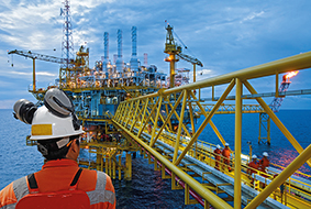
 

Viewing all 299 articles
Browse latest View live