Quantcast
Channel: Engineer Live - Production/Processing
Viewing all 299 articles
Browse latest View live

Success on the sea floor

$
0
0

Marcel Rexin reveals a product portfolio designed with the aim of preserving the natural underwater environment

Before the invention of echo sounding, many people imagined the ocean floor to be an even surface. Only later was it realised that in some places this ocean floor is just as mountainous as surfaces on land. Hidden beneath the waves are reefs, mountains, chasms, trenches and channels, posing a considerable danger to shipping. With his Secrets of the Sea TV series, which ran for 13 years, the marine explorer Jacques Cousteau brought closer to millions of viewers this dangerous, but also fascinating, underwater world. Today, fascination with the sea has not lost its appeal. With its Maritime Service, Parker Hannifin contributes aims to make shipping and offshore platform construction safer and protect the environment.

Dimensional control

Dimensional control encompasses the capture, processing and presentation of geographic and geometric information. This data later serves as the basis for the construction, prefabrication and joining of structures, plus their verification and inspection.

Subsea measurement, known as underwater metrology, is carried out with the help of photogrammetry. Aided by its custom-made camera solution, Parker creates photos and measurement diagrams with which the spatial position or three-dimensional form of an object can be determined.

Parker also performs verification of offshore vessel navigation instruments to ensure high precision at sea surface as well as seabed. All navigation instruments and sensors are surveyed into the vessel’s local coordinate system. The local coordinate systems are then transformed into a global coordinate system.

The specialists at Parker perform detailed seabed mapping using high resolution multi-beam echo sounders. The surveys provide seabed information for supporting underwater construction work such as wind mill sites, cable routes, pipeline routes, dredging and safe navigation. The company uses the Olex MBES system, a real-time system for the modelling and visualisation of the multi-beam echo sounder measurements. It is used for seabed surveys of harbours, river mounts and shorelines. The measurements are modelled into digital terrain models (DTM) that are used to produce topographical maps.

Maritime Service supplies the PMS position monitoring system, which improves safety during the loading of crude oil offshore. Connecting the flowmeter, if installed on the shuttle tanker, to the PMS enables full control of the oil flow between installation and shuttle tanker. Comparing flow received with flow information from the installation, with alarms, can avoid oil spill into the sea.

By integrating the Maritime Service unit into the organisation, the circle of Parker products and services for marine applications has been expanded.Thus the Parflange F37 flange system is used in the offshore sector for piping systems in a variety of vessels, such as suction dredgers and working vessels for the installation and supply of oil platforms. The flange programme is complemented by the high performance flanges (HPF) system – a mechanical flange system for the most stringent demands.

Total piping solution

Parker offers a solution for hydraulic systems with its complete piping solutions (CPS). From consultation on design and pre-manufacture through to delivery and installation, customers can decide whether they require a complete service package or just a part.

Modern CAD systems can process all current 3D and 2D data formats and simulate installation situations. Projects are worked out in accordance with requirements laid down by the customer or by work done in co-operation with the customer. These cases can be concerned with new installations or with modernisation programmes. The necessary recording of tube dimensions is carried out via a modern dimensioning system directly on site. It is possible to transfer this data to a CAD system. Data from the dimensioning system is later installed into the quality control system.

Once the data required for production is established, it is transferred to production machines. Tubes with dimensions Ø6 x 1mm up to Ø190 x 20mm (thin-walled Ø220 x 6mm) are manipulated on the bending machines available.

CNC-controlled machines are available. Tube-end machining is carried out based on internal standards. Tube cleaning complies with ISO Standard 4406/NAS 1638.

Prefabricated tubing line systems are delivered to the address specified by the customer. Their installation takes place in accordance with the parameters and operations laid down in the installation handbook and can be done either by Parker after notification or by the end customer.

For more information at www.engineerlive.com/iog

Marcel Rexin is with Parker Hannifin.

Images: 

Best-suited sensors

$
0
0

Leila Briem explains how to specify encoders and sensors to save space, boost efficiency and cut costs

In an industry where fluctuations in supply and demand can drastically effect drilling operations, the need to design more streamlined feedback systems is greater than ever. This means that all players, from the OEMs of drilling equipment down to the companies that build the components, need to strive to design products that boost efficiency, improve safety and lower the cost of ownership. Top among the demands for position sensing feedback devices for oil and gas operations are features such as space-saving packages, high shock and vibration resistance, extended temperature operation, superb sealing and multiple hazardous area certifications.

Many oil and gas applications exist in potentially explosive atmospheres where having explosion-proof and flame-proof rotary encoders that can operate directly in Division 1, Zone 1 environments is required. Having hazardous area rated encoders and sensors that have been triple-certified (UL, CENELEC/ATEX, and IECEx) helps simplify the certification process of an entire assembly, and saves costs in obtaining additional approvals to comply with international safety regulations. The tricky thing about designing explosion-proof and flame-proof devices is that the housing naturally needs to have a thick and more bulky construction. With the aim of keeping the overall size of equipment (such as top drives) as compact as possible, explosion-proof encoders designed in extremely low profile packages to take up less shaft space provide a more fitting solution (pun intended) than comparable larger alternatives. Compact encoders are also ideal for mud pump applications where the pumps are situated back-to-back because their low profile design allows space for installing a feedback device.

OEMs continue to demand higher performance from industrial encoders especially in drilling applications where shock and vibration are harsh. Encoders with high shock resistance, upwards of 250G, are crucial for reliable operation. Encoders on these applications are often installed behind motors, close to the brake, where a lot of heat is generated. The capability of operating in temperatures of up to +85°C (185°F) is a key requirement to demand of encoders to prevent component failure. Hard-anodised housings and IP66 levels of sealing also help to extend component life by protecting from dirt, moisture and corrosion. Removable terminal boxes simplify installation and minimise time in the field, while improved electronics that protect against wiring errors can prevent encoder failure.

Another way to boost efficiency in applications such as pipe handling and iron roughnecks is to use an explosion-proof Hall effect sensor instead of relying on multiple proximity sensors for positioning. A rotary Hall effect sensor can provide constant and accurate position feedback that allows for better speed control and increased productivity. For example, a Hall sensor would allow pipe-handling equipment to operate faster throughout its movement and then slow as it reaches the end of its travel. Furthermore, using only one Hall sensor on an iron roughneck eliminates the need for multiple proximity sensors, which not only provides more accurate feedback but also reduces cost. Using Hall effect sensors for zone control can also increase safety in drilling equipment operations because the exact location of the moving piece of machinery will be known at all times, reducing the likelihood of a collision, either with equipment or operators.

For more information at www.engineerlive.com/iog

Leila Briem is with BEI Sensors, a brand of Custom Sensors & Technologies (CST).

Images: 

Solution showcase

$
0
0

Roger Bours highlights a range of reliable and cost-effective operations in oil and gas.

Around the world, customers demand reliable performance from tools used in drilling, completion and production of oil and gas. Whether the application is onshore or offshore, topside or downhole, upstream, midstream or refinery, suppliers in this sector require a high level of expertise if they are to succeed.

Fike’s innovative and reliable pressure-activated products are responsible for significant improvements to drilling, completion and production operations in downhole operations. The company has pioneered the use of rupture/burst disc technology to create innovative devices that provide superior performance over less precise technologies.

Hydraulic tubing drains for use with deep hole drilling tools, downhole devices and other oil and off shore drilling applications provide an accurate method to equalise the fluid level in tubing strings, without mechanical manipulation. HTD rupture discs, used as standard equipment, drastically reduce the frequency of stuck tubing strings, having to pull wet strings and other oil field equipment and tubing concerns.

Cost-effective hydraulic tubing drain rupture discs offer a number of benefits, including: providing a positive indication of open drain; eliminating unreliable, shear pin devices; and resisting corrosion for increased reliability and cost-efficiency.

Meanwhile conventional pre-bulged rupture discs  are popular for a number of oilfield pressure relief applications. For instance, separator process vessels are known to experience overpressure conditions that could lead to dangerous, even catastrophic, events. The versatile Fike CPD rupture disc provides for depressurisation of vessels, emergency relief of processing equipment and disposal of vapours by vent. And the installation of the rupture disc can protect typical wellhead hook-ups when flow lines become plugged or if valves are inadvertently closed.

The CPD rupture disc has no moving parts, making it reliable under even severe operating conditions, and offers a sub-millisecond response time for critical pressure relief. The rugged CPD rupture disc is ideal for pressure relief protection and pressure activation in many oilfield applications, including separators, storage tanks, filtration systems, water knockouts and in wellhead protection.

Rupture disc holders

For safety performance and easy installation/breakdown in oil field applications, select Hammer Union and Union Type rupture disc holders for pressure relief needs.

Hammer Union rupture disc holder, or Wing Nut Union, is designed for installation locations that are hard to reach. The proven design allows for quick, easy installation and dismantling of units. Built to withstand the force of a hammer for optimal field use, the Hammer Union is superior in surface production and drilling operation applications.

Designed to accept a Fike CPD rupture disc, the Hammer Union rupture disc holder features a 30° angular seating surface.And it is this feaure that provides the compression necessary to clamp the rupture disc securely into place. The holder will also accept most discs using the industry standard 30° seat.

The Union Type rupture disc holder is a three-piece unit consisting of a base flange (inlet), a holddown flange (outlet) and a union nut. The 30° angular seating surfaces of these holders are machined to grip conventional pre-bulged P/CPV series and HO/HOV series rupture discs. The base and holddown flanges grip the rupture disc while the union nut provides the compression necessary to create a metal-to-metal seal. These rupture disc holders can be incorporated into a pressure system by welded or threaded connections, or any combination of the two.

Downhole power generation tools

Using a variety of propellants, Fike has formed an exclusive line of power generation tools. As a result of innovative, gas-generating technology, the company can help provide power to downhole devices, deep hole drilling tools and other oil field applications.

For more information at www.engineerlive.com/iog

Roger Bours is with Fike.

Images: 

High-pressure compression cooler

$
0
0

Push Dhillon reports on a heat exchanger designed for maximum uptime in minimum space

Offshore, more than anywhere, uptime is critical. Equipment fouling, failing or scaling can cause expensive downtime, loss of production or even safety- and environmental hazards. Truly robust high-pressure heat exchangers that can fit a large thermal duty into a small footprint but remain readily accessible for all kinds of maintenance have not been available – until now.

When it comes to heat exchanger technology for high-pressure gas cooling, offshore oil and gas producers have thus far been limited to choosing between bulky shell-and-tube heat exchangers and the super compact printed circuit heat exchangers (PCHE), with their micro channels. Both technologies have their advantages, but also clear drawbacks.

Being highly compact, the PCHEs are more prone to fouling, as the fine flow channels are easily blocked. When that happens, efficiency and then output are reduced. In the worst-case scenario, fouling may even cause unplanned production stops. To deal with the fouling and scaling, a carefully monitored maintenance schedule is usually set up, including multiple identical units being rotated and shipped onshore for service, which unfortunately adds unnecessary cost and effort.

No more fouling problems

“Preventing and minimising the effect of fouling and scaling in the flow channels has been one of our top priorities in designing the DuroCore high-pressure offshore compression cooler,” says Magnus Hoffstein, manager Business Unit Gas at Alfa Laval. “To start with, the corrugated plates create turbulent flow, minimising the risk for fouling. Should there be fouling, however, the large open channels in the DuroCore are more forgiving, ensuring long, trouble-free operation without losing efficiency due to scaling on the cooling medium side or fouling on the gas side. The discrete micro channels in a PCHE can become completely plugged, and that’s a risk we completely eliminate.”

With the solution’s large channels, the need for sophisticated filtration will also be less pronounced, and a larger mesh makes maintenance easier.

“This new system is specifically designed to withstand variations in temperature and pressure,” explains Hoffstein. “To accomplish that, we had to move away from the traditional plate-and-shell design with its weak, peak-stressed areas. Contrary to the traditional corrugated plate-and-shell pattern, DuroCore’s ‘roller coaster’ plate pattern is equally strong in all directions. The result is a plate pack that is extremely robust against both thermal and pressure fatigue, even against extreme shocks.”

With shell-and-tubes, there is always a risk for tube vibrations causing leaks. The DuroCore eliminates that risk, as there are no tubes in the heat exchanger and the plate pack is designed not to vibrate.

“The key to the product’s ability to reliably master the challenges of offshore production lies in the design,” says Hoffstein. “By using large channels in the heat exchanger, we have designed away the need for frequent maintenance due to fouling and scaling. Yet the plate technology allows us to keep the unit compact, compared with a shell-and-tube for the same duty, saving precious deck space. We have also addressed the operators’ need for quick and easy maintenance, even offshore, by providing a core that is easily and entirely removable, with all its welds accessible for visual inspection.”

The heart of the cooler is a cylindrical core of corrugated, laser-welded heat-transfer plates in stainless steel or titanium, depending on the cooling medium. The gas enters the plate pack through the side connection, while cooling medium flows in from the bottom via the central connection.

Offshore gas compression is a demanding and process-critical duty where both PCHE and shell-and-tube heat exchangers have their pros and cons. With the DuroCore solution, Alfa Laval has focused on the operators’ need to keep production up and running, without interruptions. Hoffstein concludes: “DuroCore will solve many of the operators’ problems in offshore gas compression cooling. We can help them perform at their best.”

For more information at www.engineerlive.com/iog

Push Dhillon is with Alfa Laval.

Images: 

Innovations in tubing

$
0
0

Meeting the evolving demands of precision tubing for the oil and gas industry. By Brian Mercer

The history of the oil and gas industry is one of constant evolution. The sector has long demanded – and continues to demand – new technological solutions to new problems. The oil and gas industry has seen a drive to exploit fields in increasingly hostile environments, from the first subsea drilling in the 1970s through to the deepwater challenges of the present day, where seawater and sour crude oil can make extraction particularly hazardous. Moreover, with the recent slump in oil prices, operators are looking not only for solutions to new technological problems but also products that deliver the most cost-effective use of resources.

Escalating requirements

How can equipment suppliers, charged with the responsibility for developing and delivering solutions to these ever-escalating requirements, succeed in meeting such challenges consistently? For Fine Tubes and Superior Tube, manufacturers of precision tubing for the most critical applications, the answer lies in having the experience to innovate.

From the early days of North Sea oil production, the sister companies have been at the forefront of meeting the needs of their customers, manufacturing corrosion-resistant tubing with tight tolerances that minimise the risk of production downtime resulting from the need to install replacements. In addition to North Sea projects, Fine Tubes has recently supplied specialist tubing for the development of fields in Norway, Nigeria, Australia and a number of the GCC countries in the Middle East.

Key approaches

One of the key approaches to meeting operational requirements has been the use of exotic alloys, including: austenitic, super austenitic, duplex and super duplex stainless steels; titanium grades; and nickel alloys.

The aim is to produce tubes that can withstand operating pressures of up to 60,000psi. Both Fine Tubes and Superior Tube regularly supply precision tubing in stainless steels 904L (UNS N08904) and 6Moly (UNS S31254), as well as nickel alloy 625 (UNS N06625) and alloy 825 (UNS N08825) for global offshore and onshore projects.

With tensile strengths greater than 220ksi (1,515 MPa), the tubing can be manufactured in sizes from 1.6mm (0.063in) OD up to 63mm (2.475in) OD.

Seamless, straight length, precision tubing is produced for instrumentation equipment as well as onshore control panels, topside processing facilities, and offshore subsea manifolds and templates up to 2,000m under the sea.

Coiled tubing is produced for downhole hydraulic control and chemical injection lines, subsea hydraulic power and chemical injection lines, and smoothbore control lines used in fibre optic applications.

Fine Tubes is a member of the highly influential Advanced Well Equipments Standardization Group (AWES), helping to set industry standards. For example, the company has been a major contributor to the development of a new recommended practice for the design, manufacture and testing of tubing encased conductor (TEC) cables and control lines.

TEC is an armoured electrical cable used to provide power to, and/or return a signal from a downhole tool. It is typically encased in a longitudinally seam-welded metallic tube in a non-annealed (cold-worked) condition. The new standard will be published in August 2015 and is another demonstration of Fine Tubes’ commitment to excellence in critical application design.

Continuing to innovate in the oil and gas arena, development plans for both tube mills include:

An evolution of the alloy 825 grade for control line tubing with higher corrosion resistance and mechanical properties

New capabilities in 1/8˝ fibre armouring for distributed temperature sensing (DTS) and distributed acoustic sensing (DAS) systems for monitoring shale gas applications, complementing the portfolio of ¼˝ tubing encased conductor (TEC) and tube encased fibre (TEF) cables.

Continued development of up to ½˝ diameter armouring for steam-assisted gravity drainage (SAGD) heater cables and possible ‘hybrid’ lines containing both copper signal and fibre optic components.

Since being acquired by Ametek, both tube mills formed a partnership that enables them to optimise the manufacturing locations for their range of high-performance tubing products and significantly reduce lead times in key areas.

“Our engineers work closely with major oil and gas companies across the globe to develop specifications for innovative new products and help customers solve their technical challenges. We encourage customers to reach out with their needs, wherever in the world precision tubing is required,” concludes Mark Ayers, director, Oil & Gas Products.

For more information at www.engineerlive.com/iog

Brian Mercer is with Fine Tubes in the UK and Superior Tube in the USA.

Images: 

Protecting sulphur storage tanks

$
0
0

Juan Lopez Galera and Anna Michael outline the merits of high-temperature linings for sulphur storage tanks

Molten sulphur is present in an ever-growing range of industries and liquid sulphur storage tanks are used worldwide in crude oil refineries and natural gas plants to store liquid sulphur in very large volumes. Sulphur storage tanks are most commonly utilised as part of the gas treating system in sour crude oil refineries and gas sweetening facilities to temporarily store liquid sulphur produced in the sulphur recovery plant. These tanks are usually field erected and most commonly constructed of carbon steel.

Even though in recent years there has been major progress with regards to the mechanical design of sulphur storage tanks, they are still plagued with corrosion issues and internal corrosion is considered to be the main cause of longevity and safety issues. Unlike external corrosion that can be easily identified, internal corrosion is out of sight and can therefore go unnoticed, causing catastrophic consequences. As a result of internal corrosion, sulphur storage tank service life has been reported to be as low as five years, although general storage tanks demonstrate a life of 30 years.

Sulphur storage tank failures not only lead to loss of revenue and increased costs through downtime and replacement, they can also have a critical human health and environmental impact.

Corrosive environment

The corrosion mechanisms vary according to the design and service conditions, but the most common cause for internal corrosion is the deposition of solid sulphur on the interior surfaces of the tank together with the presence of liquid water. The combination of these two components creates the phenomenon of wet sulphur corrosion that can cause severe attack to the carbon steel, especially when the hydrogen sulphide (H2S) concentration levels are high.

To keep the sulphur in a liquid state, the storage tanks are heated at a temperature between 257°F (125°C) and 293˚F (145˚C). Insufficient heating and external climatic conditions, in combination with missing insulation will cause temperature variations within the tank. Failure to maintain the desired temperature at the steel surfaces in the vapour space of the tank will lead to the solidification of the sulphur fog. The concentration of solid sulphur at the interior side walls, the roof and the vent nozzles will then cause severe corrosion that will propagate in depth and length.

After solidifying on the surface, the sulphur will act as an insulator contributing to further cooling of the surfaces. As the temperature continues to fall, traces of condensed water, formed by oxidation of hydrogen sulfide, will react with the solid sulphur and the iron from the tank walls, creating the ideal environment for the formation of iron oxide (Fe2O3) and iron suphide (FeS) that further accelerate corrosion.  

Protective linings

Field experience has shown that the corrosion mechanisms and conditions can be minimised or eliminated by employing protective internal linings.

The first step of Belzona’s high temperature lining research project was the introduction of hand-applied Belzona 1591 (Ceramic XHT) in 1998, and spray-applied Belzona 1521 (HTS1) in 1999. Over the following 16 years, the company’s R&D department analysed data from the field and researched innovative technologies and filler systems. This research has culminated in the introduction of its next generation of high-temperature vessel linings in March 2014, hand-applied Belzona 1593 and spray-applied Belzona 1523.

These two epoxy linings are designed to provide long-term corrosion and chemical resistance to equipment operating in continuous immersion at temperatures up to 140°C and 160°C, respectively. The two-part materials consist of an epoxy novolac base and a polyamine solidifier that, when mixed and cured, produce a very tightly cross-linked density.

The lining’s network is additionally supplemented by a novel secondary cross-linking mechanism initiated at temperatures above 90°C that further increases the cross-link density of the polymer matrix, making it even more difficult for the attacking reactive molecules to permeate through the film. Consequently, the materials demonstrate excellent resistance to liquid sulphur, sulphur dioxide (SO2) and hydrogen sulphide (H2S), as well as to the small amount of sulphuric acid (H2SO4) that may be present in a sulphur storage tank.

The high cross-link density required for coatings to achieve their high temperature immersion resistance can make conventional materials rigid and susceptible to cracking during thermal cycling and substrate flexing. Belzona 1523 and Belzona 1593 overcome this by the incorporation of rubbery domains that offer flexibility and inhibit crack propagation.

Excellent adhesion

The two linings demonstrate excellent adhesion. Belzona 1523 exhibits a tensile strength of 13.7 MPa and elongation rate of 0.54% when cured and tested at 100°C, while Belzona 1593 exhibits a tensile strength of 11.2 MPa and elongation rate of 0.31% when cured and tested at 160°C.

Since the materials can be deformed when under radial, circumferential and longitudinal stress, they preserve their integrity, move in sympathy with the substrate, and reduce material ruptures, breaks and fissures.

It has been proven that during the application of solvent-based coatings, issues can arise due to solvent retention within the film. In this case, solvent can be trapped within the applied linings and eventually evaporate leaving behind a void, which can then be filled by the system fluids causing bubbling and blistering. This is not the case with the two new linings since they are solvent free and thus also environmentally friendly.

Juan Lopez Galera and Anna Micahel are with Belzona Polymerics

Images: 

A ‘how to’ guide to breaking a pipeline

$
0
0

Neil Parkinson provides an alternative view of pipework vibration management

Some incidents are guaranteed to make headlines, never more so than at COMAH (Control of Major Accident Hazards Regulations) and OSCR (Offshore Installations (Safety Case) Regulations) sites, which have the ability to turn even the smallest incidents into disasters.

Available data for individual onshore plants suggests that in Western Europe, between 10 and 15% of pipework failures are caused by vibration-induced fatigue while offshore, the Health & Safety Executive (HSE) reports than more than 20% of hydrocarbon leaks are caused by piping vibration and fatigue. In 2012, 431 serious offshore incidents were reported, of which nearly 30% involved hydrocarbon release. More than 50 of these incidents were classed as major, and in total 33 were attributed to pipework failure. Vibration-induced fatigue clearly represents a serious risk category, but how exactly were these pipelines broken?

If asked to break a paperclip, most people would probably bend it back and forth, or perhaps rub it against another surface until it wore through. One might pull it until it snaps, or use tools to cut it through. Although pipework is far larger and more complex, individual molecules of steel behave the same way in a pipeline as they do in a paperclip – meaning that pipelines can fail as easily as a paperclip can be broken. Bending a paperclip back and forth has the same effect as low cycle fatigue in pipework, leading to vibration fatigue over time. Rubbing a paperclip to wear it down through friction is equivalent to fretting in pipework. Static overloads and pressure surges in pipelines are similar to pulling a paperclip until it snaps, while both can be subjected to mechanical damage.

Bending a paperclip back and forwards is probably the most effective method of breakage and similarly, back-and-forth vibration of pipework is one of the most common causes of failure. Mechanical excitation, flow-induced pulsation, changes in surge or momentum, acoustic-induced vibration, or cavitation and flashing are all common vibration-induced failure mechanisms, but how much vibration is significant?

The Energy Institute (EI) publication Guidelines for the Avoidance of Vibration Induced Fatigue Failure in Process Pipework contains an assessment chart to determine whether pipes are likely to suffer fatigue based on frequency and velocity of movement – and the levels for concern might be surprising. In fact, problematic vibration may not even be visible to the human eye as even at dangerous levels, prolonged movements of only 0.5mm can produce fatigue failure. For EI assessments, pipework movement must be measured in units of velocity at different frequencies. At 25Hz (1,500rpm) for example, pipework vibrating at 8mm per second would place it in the ‘concern’ range, while anything above 40mm/s is a definite problem.

Although vibration amplitudes are barely visible and velocities are relatively low, the cumulative effect over time can be significant – especially as problems can go unnoticed until a dangerous failure ‘suddenly’ occurs. However, as vibration is well understood, fatigue failures are easily preventable with a range of retrofit solutions available for a host of applications.

As the solution to vibration depends on the excitation mechanism, thorough inspection in the form of qualitative assessment, visual inspection, and specialist measurement and predictive techniques must be undertaken before determining the corrective action. The specialist measurement phase includes a variety of more in-depth tests from dynamic strain measurement and fatigue analysis to experimental modal analysis and operating deflection shape analysis, while engineers can also implement specialist predictive techniques, applying sophisticated tools and modelling to provide a more detailed assessment of the dynamics of specific pipelines throughout their lifecycles.

Although one solution to pipework fatigue is to remove the excitation mechanism altogether, this may be quite intrusive, requiring modification of the process conditions or the pipework geometry. As this disrupts production and may involve temporary shut-down, generally a non-intrusive retrofit solution is preferred as a means of providing increased resistance to vibration.

Some solutions can be very straightforward. For example, it is common for pipelines to rest on supports without any additional protection against fretting damage, in which case a secondary ‘doubler’ plate can be installed for additional support and strength without modifying any processes. However, unsuccessful or incomplete attempts at supporting pipework can result in no reduction of vibration or even an exacerbation of the problem. Small bore connections (SBCs) are frequently braced to the deck or nearby structures, for example, but to adequately counteract vibration they should in fact be braced back to the parent pipe. Bracing solutions can also be fitted in the wrong place, supporting the pipe itself rather than the main mass such as a valve, while poorly maintained bracing can loosen and return the pipework to its original level of excitation.

Another common mistake is to brace the pipework in only one plane, where vibration can cause movement in several directions. The most effective bracing system will be able to accommodate any geometric alignment of SBC, with a stiff truss design to resist movement on any plane. Similarly, for mainline pipes, visco-elastic dampers are effective in all degrees of freedom as they provide dynamic damping movement in all directions and over a wide frequency range. Another option for mainline pipework is a dynamic vibration absorber, which when tuned to the same frequency and direction as the problem vibration, will resonate to the same level out-of-phase to cancel it out. This is especially useful if there is no steelwork nearby on which to attach a visco-elastic damper.

Although pipework vibration can be difficult to visually detect, knowledge of EI Guidelines and safe limits as well as an understanding of the most effective corrective actions can prevent the kind of vibration-induced pipework fatigue that can break a pipeline and hit the headlines.

Neil Parkinson is technical director at AV Technology (AVT). 

Images: 

Mapping natural force damage

$
0
0

Ian Murray reveals how mapping can be used to add long-term value to in-line inspection

The remote nature of long-distance pipelines can expose them to a range of external loads. Earthquakes, landslides, sea bed movement, ship anchor drags, permafrost, flooding, third party damage, construction and backfill all have the potential to locally deflect a pipeline from its ‘as built’ position. Although steel pipelines exhibit small amounts of inherent ductility, any deflection from the design centre-line will impart an increased level of strain into the material. Too much deflection can cause buckling, wrinkles, damage at weld or defect locations and ultimately, failure. Although the incidence of natural force damage is comparatively low, the consequences are far greater. Natural force damage only equates to 8% of significant incidents but causes 34% of all property damage. This is because these incidents tend to result in pipeline rupture rather than leakage, hence greater spill volumes, longer downtime and increased property and environmental damage.

It is possible to identify ground conditions and locations where pipelines may be at risk of damage from bending deformation and where mapping should be considered as a matter of course. As well as any pipeline that has known or suspected pipeline movement or failure history, these include pipelines in areas of known or suspected soil settlement, wash-out or flooding, known or suspected subsidence or landslide, known or suspected earthquake or seismic activity, known or suspected sand dune migration and areas experiencing large seasonal swings in ground conditions (dry to wet, frozen to thawed). Subsea pipelines in areas of known or suspected seabed movement or areas of spanning, as well as subsea pipelines in areas of known marine activity where there is a chance of anchor drag or trawling should also be assessed routinely. There is also a major long term benefit of mapping newly laid pipelines in order to validate ‘as laid’ straightness and provide a baseline for future integrity surveys.

As it is not practical to directly measure the strain in the pipeline material along sections that might extend to hundreds of kilometres in length, the strain is calculated by considering the curvature of the pipeline. Curvature is a numerical measure of how ‘bent’ a pipeline is and it is defined as the angle a pipe turns through over distance. To assess the additional strain in a pipeline due to natural force damage or other external loading, the exact position is surveyed using an in-line inspection tool or ‘pig’ equipped with an inertial measurement unit (IMU) module. The IMU measures the pig’s movement in 3D, using three gyroscopes to measure rotation and three accelerometers measure acceleration plus gravity. The resulting data is used to determine pipeline coordinates in 3D so that pipeline curvature and resultant strain can be calculated.

Integrity monitoring

Pipeline mapping can be carried out as part of a wider integrity monitoring programme where defects and metal loss can also be identified in a single run using smart pigs. PII Pipeline Solutions’ (PII) MagneScan high-resolution metal-loss inspection for advanced length and width sizing of pitting and narrow axial external corrosion (NAEC) or CalScan EP (Caliper) tools can locate and measure dents and other geometric deviations. Inclusion of the mapping function makes little change to the overall logistics of an inspection run. The main additional activity is the provision of surveyed reference points prior to inspection, approximately every 3km (2 miles) along the pipeline. These points can be features such as block valves or temporary above-ground markers. Applying multiple inspection techniques in a single run helps to make the best possible use of a time-limited inspection window.

The mapping data provided by the IMU is used to create a 3D model of the pipeline’s actual centreline co-ordinates so that any areas of significant curvature and the associated bending strain magnitude can be identified and investigated. When repairs are required for defects reported by an inspection, highly accurate IMU coordinates enable the pipeline operator to quickly and reliably locate them via a precise GPS location prior to excavation, significantly reducing digging costs and in-field time. With a GPS accuracy of ± 1.5m the IMU mapping technology helps pipeline operators plan the most effective and efficient repair methodology by taking into account local geography and third-party constraints that may impede site access. If bending strain is found, remedial action can include exposing the pipe and replacing backfill or rock dumping. In extreme cases, extended environmental loading can lead to buckles, which need to be cut out and repaired.

Various existing industry codes consider the effect of excessive bending strain and offer guidance on limits. The presence of an axial bending stress can reduce the failure pressure of a circumferentially orientated defect including cracks and corrosion. Several fracture mechanics based methods can be used to estimate the axial failure stress for a circumferential flaw in a pipeline. The total stress due to internal pressure and axial bending load can then be compared to the estimated axial failure stress.

Reporting bending strain allows consistency of results between different pipe diameters as well as highlighting areas that may be a potential integrity threat. When a single run analysis is carried out without any historical data, the strain on the line is calculated from the measured curvature. Considering a pipeline subjected to a maximum radius bend of 400 x diameter (400D), over a 12m length the strain will be 0.125%. The 400D curvature threshold is roughly equivalent to the strain at yield for Grade B line-pipe. When historical data is available, the comparison with a previous inspection greatly improves confidence in the identification of low-level deformations. Changes in strain as low as 0.02% (equivalent to a 2500D bend, over a 12m length of pipeline) can be detected when new IMU data is compared with a benchmark dataset. During field testing the performance of PII’s IMU mapping system has been confirmed by blind tests in a client’s pipeline. In one particular test, the client exposed a 60m length of pipe and displaced the centre by 200mm. By running an IMU tool before and after the deformation, PII successfully located and sized the deformation feature in 29km of 30” pipeline. Other run-to-run comparisons have confirmed the repeatability of PII’s bending strain data, both onshore and offshore.

PII has first-hand experience of inspecting undersea pipelines that have been subjected to considerable external force. The company was recently engaged by a European customer with a number of large diameter offshore lines in its infrastructure portfolio. A single IMU inspection run was undertaken as part of a strain screening investigation to produce a baseline assessment. When the data was analysed it identified areas of deflection from the design centreline by up to 90m. Further investigation indicated that previous repairs to the pipeline had been carried out in the area that had suffered the most severe deflection, potentially causing the movement. In other areas it appeared that the damage and pipeline movement was consistent with impact from an anchor and subsequent dragging.

As well as helping to assess bending strain, IMU mapping can help pipeline operators to satisfy regulatory demands. Increasingly, regulations demand that pipeline operators document the precise location of pipeline assets. In some cases, however, records are old and of unknown accuracy, or may not include details of centreline location. Pipeline mapping can also benefit operators by determining the precise location of each girth weld and pipe feature.

Weld ruptures

Another example of where mapping has been fundamental to an operator’s integrity monitoring programme came during PII’s inspection of a spirally welded crude oil pipeline. The pipeline had been built during the 1970s in a geologically unstable area with additional ground condition variations. A number of the spiral welds had suffered ruptures due to the combined loading from internal pressure, cyclic pressure loading and axial stress from ground movement. PII’s initial inspection established that the pipeline was subject to multiple threats including internal and external corrosion, spiral weld anomalies/cracks, girth weld anomalies/cracks, dents and ovalities. Triax magnetic flux leakage (MFL), calliper and IMU ILI tools were deployed into the line to detect and quantify threats.

More than 0.5 million defects were detected by the ILI tools together with over 1,000 strain events. With such a wide range of combined threats, PII created an assessment matrix to govern assessment rules and criteria.

Increasingly, strain-based designs are being considered for new pipelines. These designs can use modern pipe material such as x80, x100 or x120. With strain-based designs it is even more important to confirm that the strain capacity of the pipeline has not been fully utilised during pipe laying. An IMU strain inspection can provide pipeline operators with this confirmation.

Strain measurement is an excellent indicator of where unknown or unexpected pipeline movement may have occurred. By identifying change of shape of a pipeline and any potential movement since the last inspection run it offers enhanced integrity monitoring and early warning of ground instability. Strain measurement also helps prevention of failures through identification of strain events and coincident features throughout the pipeline. Combined with PII’s IMU technology, it provides an invaluable integrity-monitoring tool for oil and gas pipeline operators.

Ian Murray is with PII Pipeline Solutions.

Images: 

Ultrasonic inspection of pipelines

$
0
0

Stephen R Cox and David A Harman look at the use of ultrasonics for measuring sludge and sediment levels in pipelines

In early 2013, SGS PfiNDE received a call from a client pipeline company that transports a light hydrocarbon product with entrained particulate and sediment through a 150-mile section of pipeline in Minnesota, USA. The company encountered a challenge when, after cleaning the first 20-mile section of the pipeline, the cleaning tool became blocked by, what was determined to be, the excessive buildup of sediment in front of the cleaning tool. Due to the large amount of sediment in this particular line, the tool had gathered enough sludge to completely stop any further progress of the cleaning pig.

Although the company knew the approximate location of the pigging tool used to clean the pipeline, the engineers faced three challenges. First, they needed to know the amount and characteristics of the sediment blockage. Second, they needed to know the location of the blockage in relation to the stopple tees. Third, they needed to isolate and contain the sediment, determine the sludge level and ensure that not only could the tool be removed, but that when the line was put back in service, the company would also have no further issues with flow. Initially, the use of X-ray technology to solve the issues was discussed. However, because of the diameter of the pipe, and due to the fact that it was full of sediment and product, the parties agreed that the use of x-ray technology would not only prevent them from meeting the their timeline goals, they would also not receive all of the information needed to solve their problem. After further discussions, it was decided that a technique could be developed using ultrasonic inspection technologies to determine not only location of the blockage, but also the amount of sediment in the line, its true length and other characteristics necessary to facilitate an expedited repair and return to service.

Minimal equipment

Ultrasonic inspection technologies require only a single technician with minimal equipment, results are displayed in microseconds and readily available for interpretation, and they do not pose a safety hazard. Whereas radiographic imaging requires multiple personnel with extensive equipment requirements, takes several minutes for each shot along multiple-foot sections of the pipeline, with additional time required for film development prior to interpretation of the results, and poses a safety hazard to all nearby personnel. Since the transducer can transmit and receive sound through the entire volume of materials, with an ultrasonic inspection system, a single transducer is connected to the ultrasonic instrument and is used to take measurements from any location with access to the outside surface on the circumference of the pipe.

SGS inspection technicians determined that the use of an ultrasonic scope that allowed the user to manually set the material velocity, as opposed to data logger equipment with pre-set velocity values, was required due to the problems encountered by varying velocities of the steel pipe, sludge and fluid. The equipment selected allowed the inspectors to drop the velocity down to that of water, which is considerably lower than carbon steel. The technicians also used a low-frequency, 2.25-megaHetrz transducer, which allowed significant penetration through the pipe, the fluid, and the blockage.

The technicians knew the velocity of the steel used in the pipeline was  0.230in/μs (.230 x 105). In addition, they knew that the velocity of water (as opposed to oil) is approximately one-fourth that of steel, or 0.053 in/μs (0.053 x 10⁵).

As a result, they initially set the velocity on the ultrasonic scope to water. Once the ultrasonic system was coupled to the pipe, and the pipeline diameter of 24in was taken into account, the team made the necessary adjustments in velocity settings to match the known distance from the top outside surface to the known distance of the inside bottom surface. This adjustment brought the velocity setting closer to the true velocity of petroleum product in the pipeline, which normally ranges from 0.050 to 0.055 in/µs (0.050–0.055 x 10⁵).

When inducing sound into the top of the pipe, at a location upstream of the impacted pigging tool that was clear of sediment, the technician was able to transmit ultrasonic signals through the wall thickness of pipe and the entire volume of product in the line, and receive a return signal from the bottom (180 degrees) of the inside pipe wall. Additionally, the technician was able to transmit ultrasonic signals through the entire volume of bottom wall thickness.

Utilising ultrasonic inspection technology, the technicians were able to obtain a full-volume reading.

Ultrasonic readings were taken along the entire section of pipeline containing the sediment around the circumference, enabling technicians to plot out the exact location of the sediment and determine the volume.

After final interpretation of the inspection results, it was determined that approximately 150ft of pipeline was solidly impacted with sediment build-up.

Based on the results, the pipeline company was able to accurately develop a strategy to effectively and efficiently cut and remove the specific section of the impacted pipeline.

Conclusion

Typically, pipeline companies consider the use of ultrasonic inspection technologies, such as shear wave, phased array, FAST and TOFD, only for use in high-end weld investigations, and while looking for cracks, dents and internal defects. Used properly, by a well trained, skilled technician, ultrasonic testing is appropriate for finding discontinuities below the surface of the material, such as internal corrosion, manufacturing flaws in pipeline materials, and flaws in welds.

However, with today’s generation of ultrasonic technology, inspection techniques can be developed to provide safe and virtually instantaneous results that can be used quickly, efficiently and economically obtain additional information such as fluid levels and checking for the presence of sludge, as well as many other instances where, traditionally, a more costly and time-consuming technique like radiographic inspections would have to be utilised.

Stephen R Cox and David A Harmanare with SGS PfiNDE in Oklahoma, USA.

Images: 

Superduplex stainless steel added to product range

$
0
0

In oil and gas production, the materials handling and production technology constantly comes into contact with aggressive fluids: an acidic PH value and varying gas pressure stress connecting components and filters. In hot salt water, aggressive chlorides attack the material. To provide the offshore upstream industry with a permanent, process-safe, environmentally friendly and economical material solution, Ugitech has expanded its product portfolio to include the UGI 4410 superduplex stainless steel.

Superduplex is comparatively competitively priced and meets the requirements for corrosion resistance and good pressure resistance. This Ugitech special steel also meets the NORSOK standards of the Norwegian mineral oil industry - the recognised seal of approval for the highest quality materials. 

In introducing UGI 4410 superduplex stainless steel, Ugitech adds to its product portfolio and strengthens its position as a leading provider of superduplex stainless steel long products for the oil and gas industry as well as for petrochemical applications. This new material is the certified solution for meeting the rise in demand for greater corrosion resistance that conventional austenitic and martensitic steel grades cannot provide. The deep sea has an increasingly hydrogen sulfide and acidic hydrocarbon content that directly attacks the steel used in this environment. The material is also subjected to high pressure loads. Consequently, all components in pipelines, flanges, valves and filter systems must be very high quality to ensure their safe long-term use and to prevent environmental pollution.

“UGI 4410 steel is an excellent compromise between good mechanical properties and corrosion resistance,” emphasises Marc Marticou from Ugitech. “The nickel content of this superduplex stainless steel is low compared to the one of superaustenitic stainless steel. This is what makes this superduplex steel comparatively competitive.” As a producer of special steel, Ugitech has longstanding competence in the production of highly precise profile wire for filter systems for the oil and gas industry as well as petrochemical applications.

Images: 

Specialised pumps

$
0
0

Although the price of oil has dropped in the past months, it remains the most important energy supply in the world and the demand for crude oil and natural gas has continued unabated. Interest in opening up new sources, including unconventional ones, is rising. Conveying systems must above all be adapted to the media, the environment and one another, if production is to be efficient under difficult conditions. For this reason, Netzsch has developed a range of specialised progressing cavity and rotary lobe pumps for the various fields of application in the oil and gas industry.

Netzsch pumps for the oil industry are characterised by their robust and reliable design. Construction and materials are adapted to the requirements. In the planning phase the optimal pump is specified and selected together with the customer's requirements. The use of innovative pump technologies offers safe and reliable production processes at low life-cycle costs. On this there is a large range of products available, from which the appropriate pump system for on- and offshore, for up-, mid- and downstream areas can be selected.

With new deposits still being discovered, and existing oil fields being serviced, the production of this viscous solids-containing raw material is becoming more complex. By using Netzsch drive heads and the submersible progressing cavity pump systems, many of reserves can be explored and used efficiently.

The wide range of upstream applications includes: conventional and unconventional oil production  heavy oil production; dewatering of gas wells; thermal water production; and coal bed methane/coal seam gas.

The effective use of world’s oil and gas deposits represents one of the greatest challenges of our time. In particular, Nemo and Tornado pump systems offer new opportunities to leverage dwindling oil resources, as lower quality crude oils and high viscous oils can be produced economically and efficiently. The range of mid and downstream applications covers: multiphase pumps for oil/ gas/ water mixtures with varying solid contents; injection pumps; and transfer pumps for pumping from the well to manifolds, gathering stations or over long distances with high pressure.

For more information, visit www.engineerlive.com/iog

Images: 

Pump life cycle costing

$
0
0

By applying some ‘out of the box’ thinking to capital investment, is the cheapest pump really the cheapest pump? Industry norms and pre-conceptions tend to lean heavily to centrifugal pumping systems. However, by looking deeper, in this case focusing on electrical consumption, a dramatic saving is clear. Expanding research based on The Hydraulic Institute paper Pump Life Cycle Costs: A Guide to LCC Analysis For Pumping Systems increases potential. 

This paper lists all costs associated with a pump’s life. These are:

* Initial investment costs (Cic)

Installation and commissioning (start-up) costs (Cin)

Energy costs (Ce)

Maintenance and repair costs (Cm)

Downtime and loss of production costs (Cs)

Environmental costs, including disposal of parts and contamination from pumped liquid (Cenv)

Decommissioning/disposal costs, including restoration of the local environment (Cd)

 LCC=C_ic+C_in+C_e+C_O+C_m+C_s+C_env+C_d

Based on the calculation above, there a representative saving for the selected utility alone of approximately 25% per year. 

For more information, visit www.engineerlive.com/iog

For more information visit www.rampumps.co.uk

Self-healing coating system

$
0
0

Damage to a coating is almost unavoidable during transportation, construction and service. Damage to coatings may expose the substrate to possible corrosion. Cathodic protection systems are installed to act as a back-up for coating imperfections for immersion in the case of underground pipelines. However, cathodic protection systems interact with the coating by chemical and physical phenomena, which can lead to cathodic disbondment of the coating. Corrosion may occur underneath the disbonded coating, which is a risk for asset owners. Above ground or at offshore platforms, cathodic protection is not in place as a back-up system.

Testing for cathodic disbondment of all types of regular ‘conventional coatings’ often reveals disbondment to a certain extent. Contrary to this, properly formulated visco-elastic polymer coating systems do not show any disbondment at all, due to the novel self-healing effect of small defects.

Testing for cathodic disbondment is always done on newly applied coatings, which are only tested for a short period of time, eg 30 days. Lifetime expectancy of assets however are much longer, typically 30 years or more. During its operating lifetime a coating will age and lose essential properties such as adhesive strength. This can be simulated by hot water immersion testing followed by peel- or dolly testing. Results obtained with cathodic disbondment testing do not make much sense if over time the coating spontaneously disbonds because of the its ageing processes.

Stopaq visco-elastic coating systems have proved not to be vulnerable to ageing in hot water immersion tests; values obtained with peel testing after hot water immersion at Tmax + 20°C for 100 days were similar to values obtained with non-aged test specimens and the self-healing effect – a typical property of Stopaq coating systems – still completed within the expected period of time.

For more information, visit www.engineerlive.com/iog

For more information visit www.sealforlife.com

Images: 

igitally compensated differential pressure transducers

$
0
0

DGP:50 NY LTD has announced the introduction of its Model 136/236/336 Series, a family of compact, high-accuracy differential pressure transducers.

The digitally compensated Model 136/236/336 Series can measure differential pressures as low as 20in WCD and line pressures up to 1000 PSID (69 BAR), with accuracies of up to ±0.05% FSO. They also feature high frequency response, as well as high shock and vibration resistance. Their compact design incorporates all-welded stainless steel parts and housings.

Available digital outputs include CANbus, USB, RS-485 and RS-232. Customers may also choose from various optional accuracy, process and electrical connections.

With its compact, corrosion-resistant design and exceptional accuracy specifications, the GP:50 Model 136/236/336 Series is suitable for a variety of testing requirements, including automotive and aircraft engine test stands; leak decay; liquefied natural gas (LNG) transport and storage; filtration; and flow and tank level measurements.

Images: 

Digitally compensated differential pressure transducers

$
0
0

DGP:50 NY LTD has announced the introduction of its Model 136/236/336 Series, a family of compact, high-accuracy differential pressure transducers.

The digitally compensated Model 136/236/336 Series can measure differential pressures as low as 20in WCD and line pressures up to 1000 PSID (69 BAR), with accuracies of up to ±0.05% FSO. They also feature high frequency response, as well as high shock and vibration resistance. Their compact design incorporates all-welded stainless steel parts and housings.

Available digital outputs include CANbus, USB, RS-485 and RS-232. Customers may also choose from various optional accuracy, process and electrical connections.

With its compact, corrosion-resistant design and exceptional accuracy specifications, the GP:50 Model 136/236/336 Series is suitable for a variety of testing requirements, including automotive and aircraft engine test stands; leak decay; liquefied natural gas (LNG) transport and storage; filtration; and flow and tank level measurements.

Images: 

Pitting repairs in process vessels

$
0
0

Marina Silva discusses pitting corrosion in high-temperature/high-pressure process vessels and ways to repair it. She also compares the use of hot work and repairs completed utilising cold applied epoxy materials, introducing the latest innovations in polymer technology

The costs of corrosion can be colossal, especially where safety critical equipment is concerned. When looking at the expenses associated with corrosion, particularly in the oil, gas and petrochemical industries, direct and hidden costs should be considered. The former includes equipment and part replacement whereas the latter accounts for downtime, delays, litigation and other unplanned overheads.

The most damaging form of corrosion is localised corrosion. It occurs when the steel substrate is immersed in a liquid in the presence of chemical pollutants and/or galvanic cells.

Unlike uniform corrosion where all parts of the metal surface corrode at a uniform rate, localised corrosion does not proceed uniformly and is focused at sites where corrosion proceeds much more rapidly, dependent upon the environment.

Crevice and pitting corrosion represent the main types of localised corrosion. In uniform corrosion Anodic and Cathodic sites across the surface of the steel substrate develop and are constantly changing polarity with respect to each other, resulting in an even oxidation over the entire surface.

In pitting corrosion an anode develops and maintains its electrical potential with respect to the surrounding metal. Consequently due to the large Cathode to Anode ratio, corrosion progresses rapidly forming a pit. Pitting corrosion is especially prevalent in steels that have the ability to passivate - especially in stagnant conditions where the formation of a protective film is hindered by the presence of chloride ions.

Pitting is understandably considered to be more dangerous than uniform corrosion damage because it is more difficult to detect, predict and design against. When identified, pitting damage has always been cumbersome to repair.

Pitting can be prevented and controlled by using corrosion inhibitors, cathodic protection, and protective coatings. Evidently and for a variety of reasons these protective systems have been known to fail. Once pitting occurs a solution is then required, which should be able to satisfy three basic needs: (1) quick repair, (2) ease of application, and (3) rapid return to service. Additionally, the maintenance solution would ideally withstand service conditions for a considerable amount of time.

Welding

Localised corrosion in the form of deep pits can be weld repaired to restore the original profile; however, sufficient expertise and special tools are required. If either is lacking, repairs can do more harm than good with risks of distortion, weld cracks, stress corrosion and Health and Safety risks associated with hot work.

Welding repairs carried out on metal substrates over 30mm thick must also involve post weld heat treatment (PWHT). PWHT, in some instances, may result in the loss of weld metal strength and toughness. The mechanical properties of the weld-joint may deteriorate as the vessel is repaired repeatedly. At times, PWHT takes approximately 40 hours to complete, therefore can be very costly, especially offshore. Furthermore, by welding over a metallic substrate, metal is being applied onto metal again. The original problem is not removed unless the metallic substrate is coated with an organic protective material.

Alternative to welding

Another viable alternative to repair pitting corrosion is the use of cold applied epoxy materials. These 100% solids paste grade materials have been on the market since the 1960s and have been continuously improved to withstand greater temperature and pressure levels as well as various in-service conditions. Based on positive qualification testing data, they have been successfully applied in the field in the past two decades. For instance, an amine reboiler vessel at a gas terminal in the UK suffered corrosion with heavy pitting, which was discovered in 2011 (Figure 2). The operator required the vessel to be back in service as soon as possible and was looking for an alternative solution to hot work.

A paste grade epoxy material was chosen to fill the pits and the wall was protected with a modified epoxy novolac coating afterwards. Both the coating and paste grade material were designed to achieve full curing in high-temperature immersion service, minimising downtime.

The reboiler was opened up for inspection in July 2015. No further pitting damage or corrosion were identified. Minor localised repairs were completed on the coating and the reboiler was returned to service.

Cold applied repairs: application methodology

In order to ensure fitness for service of pit filling epoxy paste grade materials, the application should be carried out in strict accordance with manufacturer’s requirements.  The contracting company must ensure that the surface is prepared correctly, the repair material is mixed and applied properly and that it is allowed to cure in accordance with manufacturer’s instructions. A typical pit filling procedure is summarised as follows.

1. All work must be carried out in accordance with the manufacturer’s instructions.

2. The vessel substrate must be dry and contaminant-free.

3. Sharp edges or irregular protrusions should be ground down to a smooth contour with a radius of not less than 0.1 inch (3 mm). All surfaces must then be grit blasted using an angular abrasive to Swedish Standard SA 2 ½ (near white metal finish) with a minimum profile of 3 mils (75 microns).

4. Paste grade epoxy material is mixed at a correct ratio.

5. The material is applied onto the substrate until original wall thickness is restored.

6.  Material is allowed to solidify at ambient temperatures before achieving full cure in service.

Historically, one drawback of using epoxy materials for pitting repairs was the amine bloom film, which would appear on the surface during cure. Bloom manifests in a form of sticky deposits and affects overcoatability and intercoat adhesion. It must be removed by first washing with a hot detergent solution followed by a fresh water wash and then frost blasting prior to the application of a protective coating atop the pitting repair, leading to extended application time and labour costs.

The latest innovation in raw materials has brought on non-bloom technology, where frost blasting of the applied material prior to the application of protective lining is not required. This feature was incorporated into the reformulated version of the Belzona 1511 (Super HT-Metal), which has been on the market since 2001. In addition to incorporating non-bloom technology, further evaluation revealed the following enhanced features:

* Frost blasting of the Belzona 1511 is no longer required when a protective lining is being applied atop with a 24-hour overcoat window, thus reducing application costs.

* Application is also simplified with mixing and application possible at temperatures as low as 10°C (50°F).

* Rubbery domains used in the Belzona 1523 and Belzona 1593 linings have also been incorporated in the polymer matrix of Belzona 1511, improving adhesion, flexibility and toughness.Tensile shear adhesion (ASTM D1002) has increased by 46% regardless of the cure temperature. Pull off adhesion has increased by 34% (ASTM D4541/ ISO 4624).

Continuous advancements in raw materials make it possible for coating and composite manufacturers to produce systems that are better value and easier to apply, at the same time minimising the risks typically associated with hot work. This way indirect costs of corrosion, including downtime, delays, litigation and other unplanned overheads, can be significantly reduced.

Marina Silva is with Belzona Polymerics Ltd

References: 1, American Petroleum Institute. Pressure Vessel Inspection Code: In-Service Inspection, Rating, Repair and Alteration. API 510. Tenth edition, May 2014; 2. GUPTE, S. V. 2004. Inspection and Welding Repairs of Pressure Vessels. [Online]. [Accessed on 13 July 2015]. Available from: http://www.ndt.net/article/v09n07/rajesh/rajesh.htm; 3. Partridge, I., Wintle, J., Speck, J. 2005. Pressure Vessel Corrosion Damage Assessment. [Online]. [Accessed on 13 July 2015]. Available from: http://www.twi-global.com/technical-knowledge/published-papers/pressure-vessel-corrosion-damage-assessment-november-2005; 4. Ferguson, K. R. 1991. Vessel Corrosion Repair-1 Weld Overlay Chosen for Corrosion Repair at Texas CO2 Plant. [Online]. [Accessed on 12 July 2015]. Available from: http://www.ogj.com/articles/print/volume-89/issue-48/in-this-issue/gas-processing/vessel-corrosion-repair-1-weld-overlay-chosen-for-corrosion-repair-at-texas-co2-plant.html; 5. Gysbers, A. C. 2014. Avoiding 5 Common Pitfalls of Pressure Vessel Thickness Monitoring. [Online]. [Accessed on 12 July 2015] Available from: https://www.equityeng.com/sites/default/files/IJ.pdf

Images: 

Compact version of cryogenic valve for marine

$
0
0

Parker Bestobell Marine, a supplier of cryogenic valves for ships, has launched a new compact version of its Float Isolation Valve (FLIV).

The compact FLIV, which is 150mm in diameter and just 600mm high, was developed to cater for the use of smaller diameter floats that are now being specified by shipyards for secondary level monitoring systems on LNG carriers.

The Parker Bestobell Marine FLIV is installed on top of the cargo tanks of LNG carriers and isolates the gauge and float from the cargo tank. These essential valves prevent boil-off gas from the cargo tanks, which could potentially be extremely dangerous.

Parker Bestobell Marine’s original FLIV valve is available in 300mm and 200mm diameters.  The first FLIV was supplied to an LNG carrier in 2007 and since then has been fitted to over 120 LNG carriers, making it the preferred choice for the majority of ships built since then.

FLIV was originally designed to work in conjunction with the secondary float system supplied by Whessoe (now Wartsila Tank Systems) and has now been adapted to work with a similar system manufactured by Henri Systems.

Images: 

Resounding success

$
0
0

Oil and gas pipelines require regular inspection to detect faults that can cause leaks. Welds in particular need careful examination as many types of weld defect can lower the overall strength of a pipeline and form a site for potential pipeline failure.

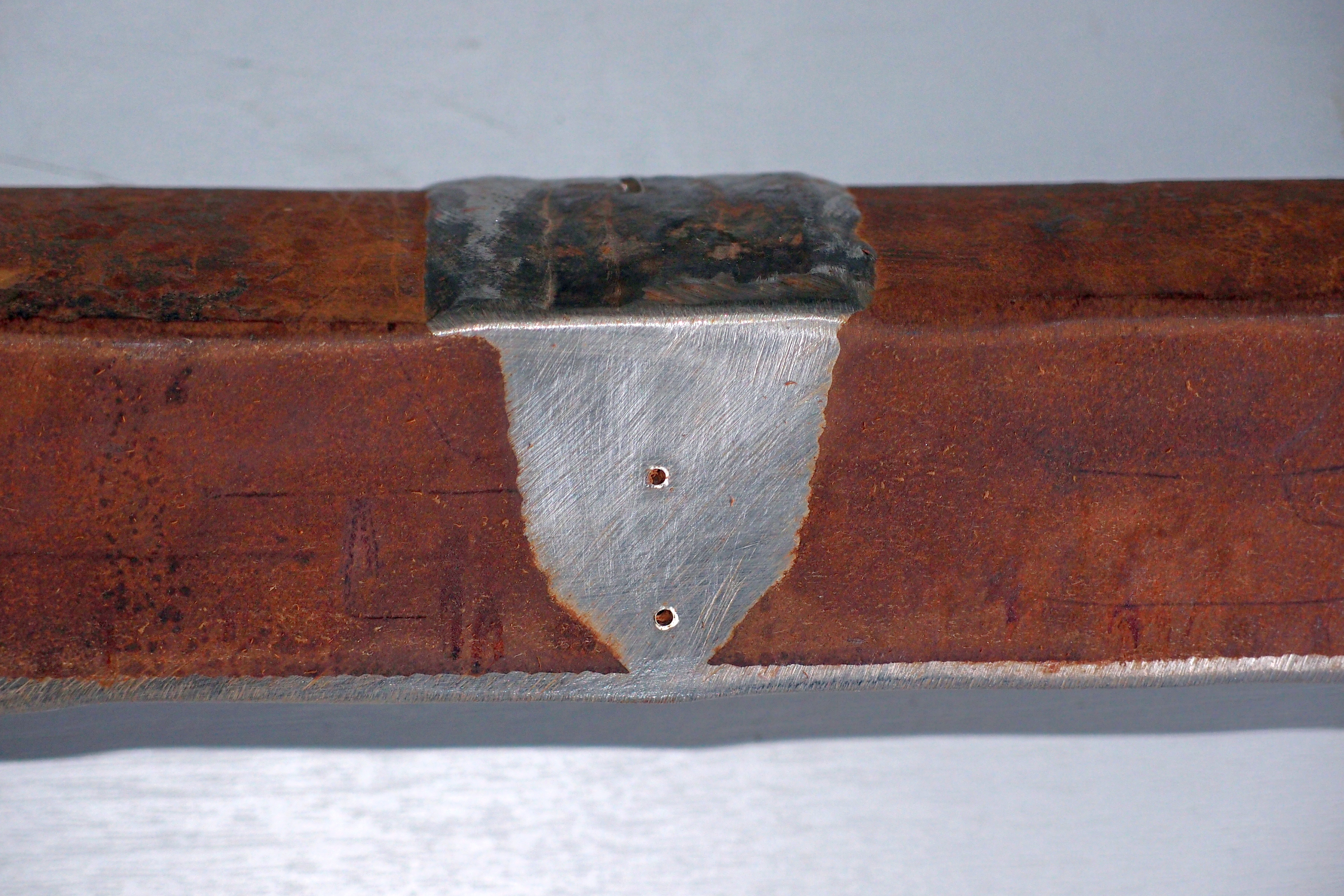
Defects can occur in a weld, either due to incorrect operation of the equipment or due to an incorrect welding set-up. Examples of common weld defects are porosity, lack of fusion, slag inclusions, root or toe cracks, and incomplete penetration. Defects can have a significant impact on the strength of a weld and therefore on the quality of the pipeline.

The most reliable and cost-effective way to ensure the quality of welding on large scales is by non-destructive testing (NDT). Depending on the weld material and its preparation, certain types of defects can be either easy or difficult to detect.

Lack of fusion can occur, for example when a bead of molten weld material fails to melt the parent material and simply solidifies on top of it. The resulting bond has a low strength. This means that lack of fusion is one of the critical flaws that need to be detected.

Detecting damage with X-rays

Radiography as the current gold standard relies on high-energy photons travelling through metal towards a detector on the other side. Any irregularities inside the component – either in the weld, the parent material or at the interface – show up as brighter or darker regions on the detector.

The main limitation of the use of radiography is the harmful effect of the radiation used. Due to the many risks to human health caused by high-energy X-rays, safeguards are needed to avoid exposure to radiation. This usually means that a large area in the direct vicinity of the inspection has to be evacuated, disrupting the work in the area of inspection.

Probability of detection is likely to be a factor when choosing a method for weld inspections. There is evidence that the contrast of defects such as lack of fusion can be low when using radiography. Contrast can be even lower when dissimilar material welds are used. This means that the probability of detection of lack-of-fusion defects is reduced, for example when a stainless steel pipe is welded with a corrosion-resistant alloy.

Phased array ultrasound

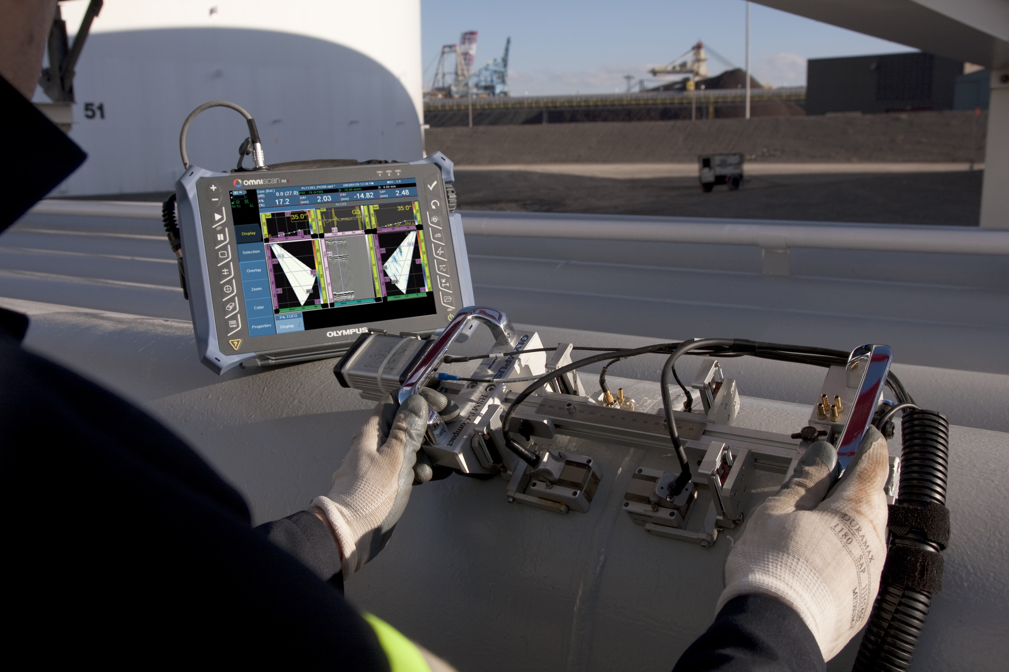
An alternative technique for inspecting welds in search of defects is ultrasonic inspection. Ultrasonic flaw detectors, such as Olympus’ OmniScan MX2 use sound waves rather than radiation to inspect components. Detection is based on the deflection of these sound waves at interfaces within the component. To maximise probability of detection – and to enable imaging and sectorial scans – ultrasonic phased array probes can be used.

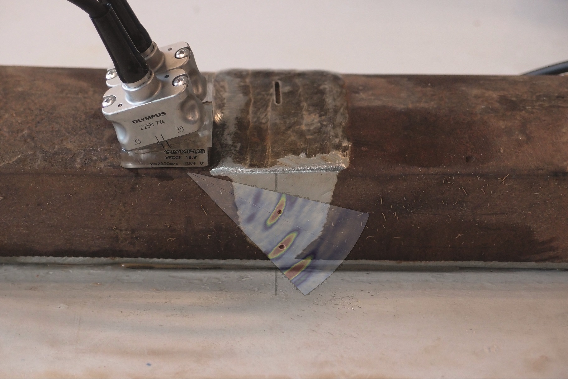
Ultrasonic transducers work by detection of high-frequency sound waves, either by the emitting transducer itself (pulse-echo technique) or by a receiving transducer (pitch-catch technique). In difficult components, such as stainless steel or dissimilar-material welds, high levels of noise are generated. In these situations, the pitch–catch technique, also known as the transmit–receive longitudinal (TRL) technique, is preferable.

Pitch-catch inspection can be carried out using either conventional, single-element probes or using phased array probes where each transducer contains multiple elements; these probes are known as dual matrix array (DMA) probes. In phased array inspections a flaw detector controls each element individually.

Among the benefits of phased array are imaging capabilities, sectorial scans and easy coverage of a weld without moving the probe back and forth. These capabilities, combined with better control over the ultrasonic beam, simplify inspection for improved probability of detection.

By eliminating the need for harmful X-ray radiation, phased array ultrasound offers improved safety compared to radiography. Phased array inspections can also provide improved detection of certain types of difficult-to-inspect defects, such as lack of fusion. This means that with ultrasonic flaw detectors, such as the Olympus OmniScan MX2, inspectors can examine large oil and gas pipelines safely and with a high probability of detection.l

Thierry Couturier is with Olympus Europa. www.olympus-europa.com


Images: 

Crystalliser vessel trial begins

$
0
0

Twister and Petronas have entered into a joint development program for the use of Twister technology for the monetisation and processing of acid gas fields containing large amounts of CO2. Part of the program is to develop, fabricate and test a skid-mounted Crystalliser Vessel for qualification, confirming the functionality and proving the concept of melting CO2 solids and producing liquid CO2 ready for reinjection. 

 
The Crystalliser vessel is similar to the proprietary Twister Hydrate Separator in that both technologies can handle a solid phase, although the Crystalliser vessel operates in a low temperature cryogenic environment. Currently Twister technology is qualifying for an offshore application for CO2 removal using a cryogenic setup. The alternative technology consists of a vast area of membranes that considerably increases the size and weight of the offshore structure. The main feature of the cryogenic approach is the generation of solid pure CO2 (dry ice). Using an adaptation of Twister’s Hydrate Separator, the solid CO2 is melted in order to enable reinjection of CO2 into the reservoir through pumps. A fully equipped skid, fabricated in the Netherlands containing the Crystalliser and test control equipment, is being transported to Malaysia to undergo qualification tests.
 
The qualification test is scheduled for Q2 2018 in Petronas' facilities in Malaysia and is a key component of the joint technology program, which includes the development of the Twister Supersonic Separator for CO2 removal. 

Tags: 
Images: 

Floatover success for Aasta Hansteen

$
0
0

Floatover equipment from Trelleborg’s engineered products operation has contributed to the successful mating of Statoil’s landmark Aasta Hansteen gas field project’s 24,000 ton topside and the world’s largest Spar FPSO platform, off the coast of Norway at Stord.

Following a 14,500 nautical mile journey from South Korea, the 24,000 ton topside for the Aasta Hansteen platform was towed from Ølensvåg to Stord on the west coast of Norway. At Stord it was floated over the seabed-moored vertical cylindrical hull of the 200 meter long, 46,000 ton Spar FPSO platform.

Trelleborg designed, tested and delivered two topside mating units with design loads of 1,500 MT each, as well as eight dual barge floatover support units with support design loads of 7,500 MT. These were essential component of the floatover system, as they acted as support points between two barges that supported the topside as it was slowly moved into position over the substructure.

JP Chia, Engineering Manager for Trelleborg’s engineered products operation, says: “Comprising Norway’s first Spar FPSO platform, the Aasta Hansteen gas field is a truly ground-breaking and challenging project. Our floatover solutions were delivered and installed safely and efficiently, ensuring a successful floatover.”


Images: 
Viewing all 299 articles
Browse latest View live